Loading...
Loading...
Loading...
Loading...
Loading...
Loading...
Loading...
Loading...
Loading...
Loading...
Loading...
Loading...
Loading...
Loading...
Loading...
Loading...
Loading...
Loading...
Loading...
Loading...
Loading...
Loading...
Loading...
Loading...
Loading...
Loading...
Loading...
Loading...
Loading...
Loading...
Loading...
Loading...
Loading...
Loading...
Loading...
Loading...
Loading...
Loading...
Loading...
Loading...
Loading...
Loading...
Loading...
Loading...
Loading...
Loading...
Loading...
Loading...
Loading...
Loading...
Loading...
Loading...
Loading...
Loading...
Loading...
Loading...
Loading...
Loading...
Loading...
Loading...
Loading...
Loading...
Loading...
Loading...
Loading...
Loading...
Loading...
Loading...
Loading...
Loading...
Loading...
Loading...
Loading...
Loading...
Loading...
Loading...
Loading...
Loading...
Loading...
Loading...
Loading...
Loading...
Loading...
Loading...
Loading...
Loading...
Loading...
Loading...
Loading...
Loading...
Loading...
Loading...
Loading...
Loading...
Loading...
Loading...
Loading...
Loading...
Loading...
The information about UPGRADE SOFTWARE for Gremsy Payload
Welcome to Gremsy Documentation Here you’ll find comprehensive manuals, user guides, and technical resources for all Gremsy products. Whether you're setting up a new gimbal or troubleshooting an issue, this is your go-to knowledge base.
If you can't find the information you need or require further assistance, feel free to contact us at [email protected] — we're here to help.
Up-to-date documentation for all current products
Step-by-step setup and configuration guides
Firmware update instructions
Troubleshooting tips and FAQs
Technical specifications and integration resources
Contact to [email protected] to get more information
Orus L Fully compatible with the Gremsy Payload Plus Android application, offering advanced control and configuration capabilities over Ethernet (UDP + RTSP).
Key Highlights
Seamless Integration with Payload Plus: Orus L works natively with the Gremsy Payload Plus app, enabling intuitive setup, real-time gimbal control, and live video preview directly from an Android device.
Ethernet Connectivity: Utilizes high-speed Ethernet interface to ensure stable and low-latency communication for both control (UDP) and video streaming (RTSP).
Precise Gimbal Control: Control Pan, Tilt, and Roll angles smoothly using the app interface. Adjust movement speed, mode switching, and gimbal behavior on the fly.
Live Video Streaming via RTSP: Stream real-time video feed from the integrated camera to the Payload Plus app using RTSP, ensuring immediate visual feedback for target framing and mission planning.
Advanced Configuration: Access full payload settings including object tracking, AI detection, camera indeep settings—all within the Payload Plus app.
For the detailed installation and connect with the Payload Plus, refer to the link below:
Orus L support connect with PC or similar device running Windows/Mac/Unbutu over USB-ETH connection in order to initial setup, settings param and troubleshooting
It will require for some configuration to have the stable connection over the USB-ETH connection
While you connect to your computer as default IP, it may change and affect to the connection, leading to loss and instability
This article will show you how to change the IP address of computer for stable connection with ORUS-L via USB connection
The information about UPGRADE FIRMWARE for ZIO PAYLOADS and VIO PAYLOADS.
Before upgrading firmware, please download the latest firmware and install requirment software:
ZIO PAYLOADS:
VIO PAYLOADS:
Camera 3
102
Camera 4
103
Camera 5
104
Camera 6
105
Baudrate:
1200
2400
4800
9600
19200
38400
57600
111100
115200
230400
256000
460800
500000
921600
1500000
Camera 1
100
Camera 2
101

Detail guides for setting up with Payload hardware.
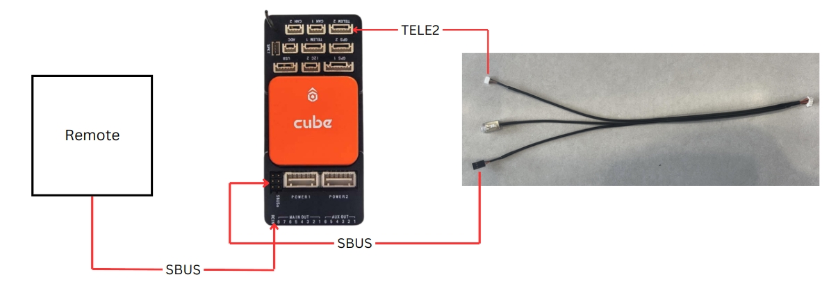
Control by Remote Controller for SBUS or PPM
ORUS L and other gremsy payload compliance with the Mavlink protocol v2 and support for the payload settings over Mavlink telementry.
It could be integrate/embedded to the autopilot software such as Qground Control easily by manual or auto ( with internet access in the first time connect).
Note: If you're running the customize software, you may need to customize the payload menu settings UI by using Payload SDK for call the API.
Detail guides for setting up with Autopilot systems
The Zio comes with a 64GB Micro SD card and this is the maximum capacity the Zio supports.
We recommend using a UHS-1 Micro SD card to minimize the delay when reading and writing high-resolution video data.
Config file set IP address of Zio and IP address of UDP stream receiver.
Config file control Zio with Ethernet.
Save images and videos.
Zio Camera Settings and Guideline
Please carefully follow the guidelines to have the proper camera settings.
ZIO supports video streaming over Ethernet.
Please update to the latest firmware and follow the following instructions .
ZIO supports control over Ethernet Telementry
Please update to the latest firmware and follow the following instructions .
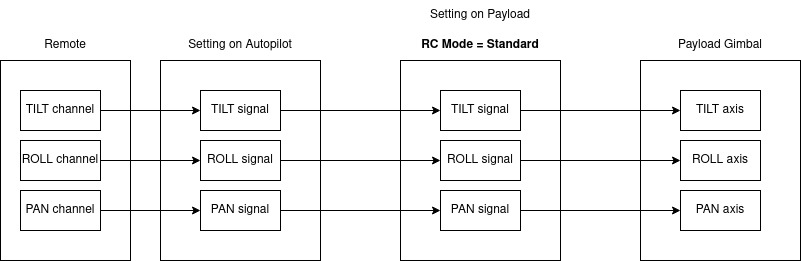
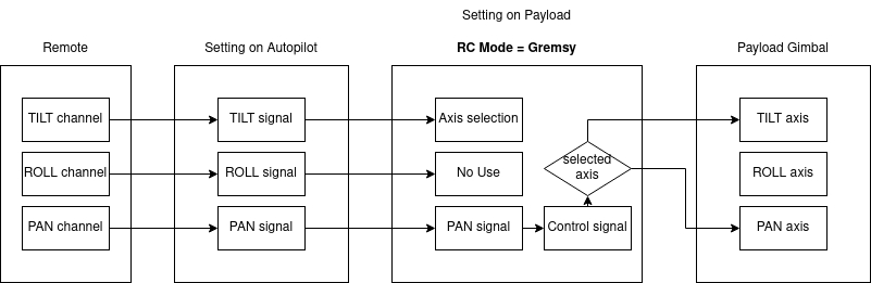
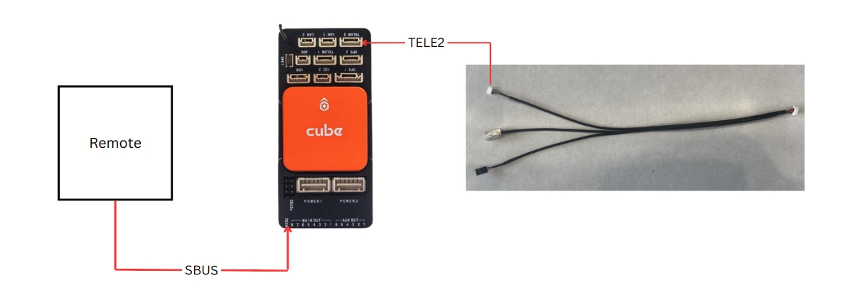
The control signal will be sent directly to gimbal via RC in the MAVlink-out protocol
The user can control 3 axis of gimbal by using 3 RC channels independently
In this case, the user only have a dial wheel to control gimbal and a button to select which axis will be controlled.
In this mode, the PAN signal will be used to control TILT or PAN axis depending on the selection change by TILT signal (assign to a button).
The ROLL axis is always '0'

🔌 Step 1: Connect the Device
Plug the device into your PC using a USB-C cable.
Your PC will automatically display a notification: L4T-README (E:) 💡 This confirms that the device is recognized.
🌐 Step 2: Access Network Settings
Go to: Settings > Network & Internet > Advanced network settings
Locate the Ethernet adapter labeled as: Unidentified network | Remote NDIS Compatible Device #2 (or similar) This is the virtual network interface created for the USB-C connection.
🖥️ Step 3: Edit the PC’s IP Address
You now need to assign a static IP address to this adapter.
Click on the Ethernet adapter (Ethernet 5 or similar).
Choose Edit IP settings.
Select Manual, turn on IPv4.
Enter the following:
IP address: 192.168.55.3
Subnet mask: 255.255.255.0
Leave other fields blank unless specified by your device documentation.
Click Save.
✅ Completed
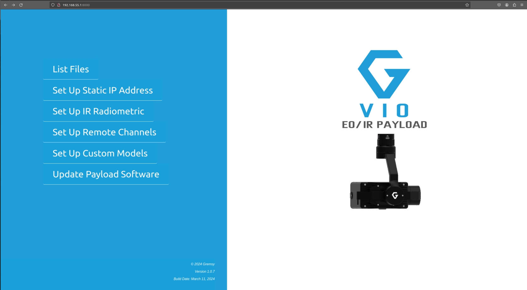
Your PC is now on the same subnet as the connected device (typically 192.168.55.x). You can now:
Access a web interface, link:192.168.55.1:8000
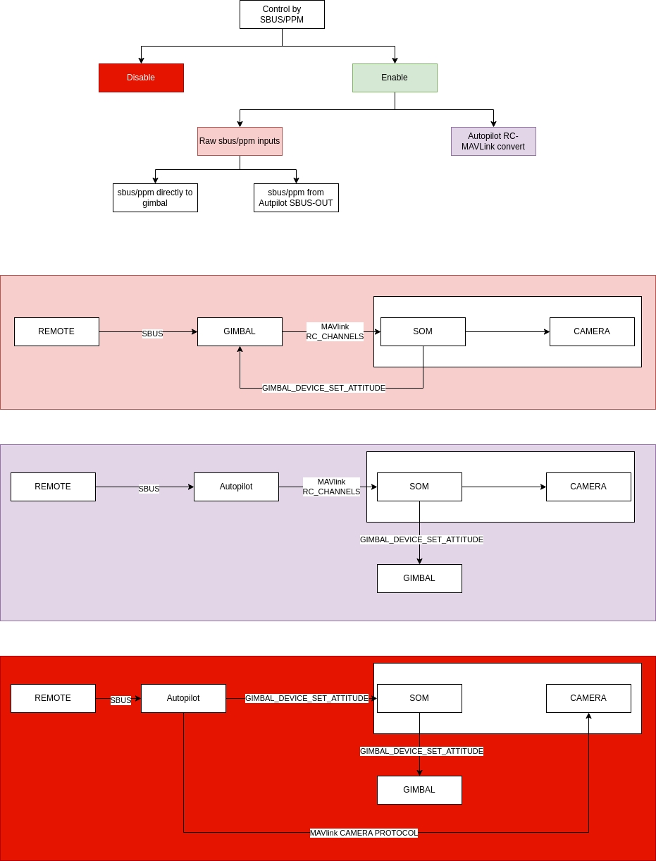
Control Mode:
Disable
Raw Input: Control Gremsy Payload by sbus from gimbal
Autopilot Convert: Control Gremsy Payload by sbus from autopilot
Image Capture: Select push button. Capture Image when pressing button
Video record: Select push button. Pressing the first time will start record video, pressing the next time will stop record video
Zooming: Select stick with 3 states. 3 states: zoom tele, stop zoom, zoom wide
Tilt: Select rotate button. Control tilt axis
Roll: currently not in use.
Pan: Select rotate button. Control Pan axis
Mode: Select stick with 3 states. 3 states corresponding to 3 gimbal mode: OFF, LOCK, FOLLOW
Return Home: Select push button. Gimbal return home when press button
Parameter Setup
Version: update to the latest version.
Support Mavlink v2 protocol
1
IP Address
2
Storage
3
General Setting
4
Video Streaming
5
PiP Configuration
Orus L Fully compatible with the Gremsy Assistance Desktop offering advanced control and configuration capabilities over USB-Ethernet for settings and testing the payload.
Use the USB-C port to stream and control the Orus-L payload using the Payload Assistant Desktop application.
✅ Step 1: Launch the Application
Open Payload Assistant Desktop v2.0.0.1 or later on your computer.
✅ Step 2: Configure RTSP Video Stream
URL RTSP: rtsp://192.168.55.1:8554/payload
Port 8554 is used for RTSP (Real-Time Streaming Protocol).
✅ Step 3: Set Communication Settings
IP: 192.168.55.1
PORT: 14566
Port 14566 is used for MAVLink telemetry communication.
✅ Step 4: Connect
Status will show: "PAYLOAD CONNECTED" if successful.
Click "Open Video" to start the RTSP stream (video feed).
Click "Connect" to establish the MAVLink link via port 14566.
General diagram of the ZIO Support page, and the steps you must go through to set it up properly. Please consult before going into details
This feature will come with the SBUS extension board from Gremsy to convert SBUS input to MAVlink message before sending to the payload.
Step 1: Connect to the Settings app via Ethernet.
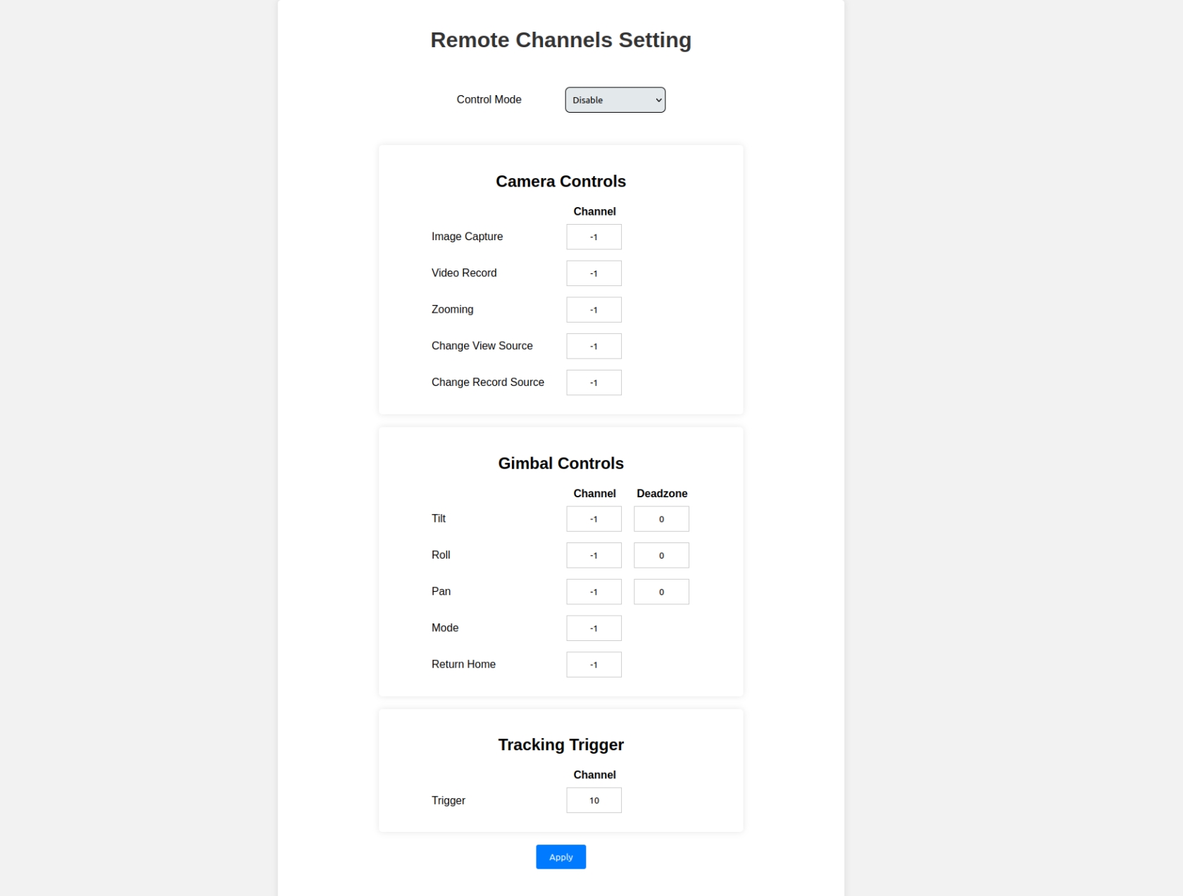
Step 2: Open "Set Up Remote Channels"
Step 3: Select the channels you want to control corresponding to the functions. The value should be between 1 and 18; if not used, please set it to default -1.
Step 4: Tilt - Roll - Pan can select "deadzone" depending on remote.
Config the micro SD-card to Zio
Remove all file .conf in the micro SD card or unplug micro SD-card from Zio
Setup app QGroundControl
Step 1: Turn on Wifi on the remote to be able to download Zio parameter list
Step 2: Enable UDP from Application Setting -> AutoConnect to the following devices
Successful connection
Zio
Zio is compatible with the Remote Control (RC) that supports the QGroundControl app (QGC). In this manual, all settings are made on Herelink Remote Control, the other controller does the same.
Zio needs to set up 2 channels to control the gimbal: one channel is for controlling rotation, and the other is for choosing the controlling axis.
Gimbal rotation control channel: CH6 (or any channels), use the wheel button on the Herelink remote:
Gimbal axis selection channel: CH8 (or any channels), use the camera button on the Herelink remote.
Orus L is designed to be highly flexible, allowing it to integrate into a wide range of UAVs and robotics platforms. With support for UART, Ethernet (UDP & RTSP), MAVLink, and the Gremsy Payload SDK, users can easily adapt Orus L to fit their specific system architecture—whether it’s a flight controller-based drone, an onboard computer, or a mobile robot.
Below are four common integration setups that demonstrate how Orus L can be deployed in real-world applications:
Ideal for traditional drones using PX4 or ArduPilot firmware.
Use USB-C (bottom of ORUS-L) to connect the Payload Web Setting.
To check the Firmware version and Software version, also configure the parameter of Payloads
How to Connect?
LINK: 192.168.55.1:8000
From the new firmware below, ZIO supports streaming and control over Ethernet along with many new updates to Autolilot and Payload SDK. Check it out in the following article.From the new firmware below, ZIO supports
Gimbal Firmware
Payload Firmware
Connect the ZIO UART to the Telem2 on the PX4 systems
Manual
Download the suitable with your software version here:
Install to the Software Camera Settings folder
E.g: QGroundControl
Auto
Connect the Ground Station/Remote which is running the software to the internet.
GREMSY UNVEILS VERSATILE, LIGHTWEIGHT EO/IR PAYLOAD FOR VARIOUS DRONE PLATFORMS
Gremsy, a front-runner in drone gimbal and payloads manufacturing, proudly introduces the Vio series, its groundbreaking lightweight, plug-and-play EO/IR payload for multiple drone platforms. The Vio series marks Gremsy's inaugural entry into advanced EO/IR payloads, featuring a 4K zoom sensor, a 640x512 radiometric thermal camera, and an integrated laser rangefinder with an impressive range of up to 3000m. Its cutting-edge features make it an indispensable tool for professionals in various sectors, from industrial inspections to search and rescue operations.
The Vio Series comes with 2 versions: Vio F1 and Vio G1.
Zio is compatible with the Remote Control (RC) that supports the QGroundControl app (QGC). In this manual, all settings are made on Herelink Remote Control, the other controller does the same.
Zio needs to set up 2 channels to control the gimbal: one channel is for controlling rotation, and the other is for choosing the controlling axis.
Config the micro SD-card to Zio
Remove all file .conf in the micro SD card or unplug micro SD-card from Zio
Setup app QGroundControl
Step 1: Turn on Wifi on the remote to be able to download Zio parameter list
Connect the ZIO UART to the Telem2 on the Ardupilot systems
Select the desired isotherm display mode:
Disable – Turns off isotherm overlays
Upper & Lower – Highlights areas above and below defined temperature thresholds
Medium – Highlights areas within a specified temperature range
Enter the lower threshold for isotherm display (°C)
Enter the upper threshold for isotherm display (°C)
💡 Use precise values to isolate thermal anomalies or regions of interest.
Choose the appropriate thermal measurement range for your application:
-20℃ ~ 150℃ – Standard range for general thermal tasks
-20℃ ~ 550℃ – Extended range for high-temperature environments
Click “APPLY” to confirm and apply your isotherm configuration. The thermal display will immediately reflect the new settings.
After selecting the correct timezone, click the “APPLY” button to confirm and save your settings.
The system clock will automatically update to reflect the chosen timezone.
Correct timezone configuration is critical for:
Accurate flight logging and mission timestamping
Compliance with regulatory reporting requirements
Synchronization with ground control and data servers
For operations spanning multiple regions or time zones, ensure the system timezone is updated accordingly prior to deployment.
Firmware Version
Latest
Required for MAVLink v2 support and gimbal features
MAV_1_CONFIG
TELEM2
Assign MAVLink instance 1 to telemetry port 2 (TELEM2)
SER_TEL2_BAUD
115200 8N1
Set TELEM2 baud rate to 115200, 8 data bits, no parity, 1 stop bit
MAV_1_FORWARD
1
Enable forwarding of MAVLink messages
MNT_MODE_IN
RC
Mount input mode: manual control via RC channels
MNT_MODE_OUT
2
Mount output mode (specific to hardware/protocol)
MNT_RC_IN_MODE
1
RC input mode: angular control
MNT_MAN_PITCH
AUX3
Manual control for pitch (tilt) assigned to AUX3
MNT_MAN_ROLL
AUX2
Manual control for roll (zoom) assigned to AUX2
MNT_MAN_YAW
AUX1
Manual control for yaw (pan) assigned to AUX1
RC_MAP_AUX1
Channel 6
Maps RC channel 6 to AUX1 (yaw control)
RC_MAP_AUX2
Channel 7
Maps RC channel 7 to AUX2 (zoom control)
RC_MAP_AUX3
Channel 8
Maps RC channel 8 to AUX3 (pitch control)
COM_RC_IN_MODE
3
RC input mode blending (e.g., RC + MAVLink)
6
Localization
*
Factory Reset
*
Restart Payload
*
Reboot System
*
Export Setting
*
Import Setting
Then the payload settings will be auto-downloaded and install to your device


This section covers general configuration options to tailor Orus-L’s behavior and measurement units to your operational needs.
Select the preferred unit of measurement for distance readings:
Meters
Yards
Feet
Miles
Kilometers (km)
Choose the format for displaying GPS coordinates:
Decimal Degrees (DD) – e.g., 41.40338, 2.17403
Degrees, Minutes, Seconds (DMS) – e.g., 41°24'12.2"N 2°10'26.5"E
Degrees Decimal Minutes (DDM) – e.g., 41°24.2028', 2°10.4418'
Enable or disable automatic zoom during object tracking:
Enable – Zooms automatically to keep the target centered and sized
Disable – Zoom level remains fixed regardless of target movement
Specify where the camera configuration is sourced from:
Offline – Uses onboard definitions without requiring internet access
Online – Loads updated definitions from the cloud when connected
After configuring the above options, click “APPLY” to save the settings. Changes will be applied immediately or after a system restart, depending on the option.
This section provides configuration options to optimize the infrared (IR) camera's display, measurement accuracy, and Flat-Field Correction (FFC) behavior.
Adjust how the IR image is displayed on screen:
Original – Maintains the sensor’s native aspect ratio
Full Screen – Scales the image to fill the display
Enable or disable visual overlays for measurement regions:
Enable – Displays measurement boxes on the IR image
Disable – Hides all ROI overlays
Select the size of the temperature measurement region:
Small
Medium
Large
Full Screen
📌 Choose a smaller ROI for precise spot measurements or larger regions for broader thermal averaging.
Control how thermal noise and image uniformity are corrected:
Auto – Automatic calibration based on internal logic
Manual – User-triggered calibration
External – Triggered by external signal
External with Auto Table Switch – Uses external trigger and auto compensation table selection
Set how frequently FFC is triggered in Auto mode.
Example: Enter
60to run FFC every 60 seconds.
Set the minimum change in temperature that triggers an automatic FFC operation.
Select the number of frames used to integrate the image during FFC:
2 Frames
4 Frames
8 Frames
16 Frames
Higher values improve uniformity but may slightly delay frame refresh.
Click “APPLY” to confirm and apply your IR camera configuration. Settings will be used immediately or after the next FFC trigger.
Height of the PiP window
1 to 512 pixels
Position X:
Enter a value between 0 and 1280.
This sets the horizontal position of the PiP window's top-left corner relative to the left edge of the screen.
Position Y:
Enter a value between 0 and 568.
This sets the vertical position of the PiP window's top-left corner relative to the top edge of the screen.
Width:
Enter a value between 1 and 640.
This defines the width of the PiP window in pixels.
Height:
Enter a value between 1 and 512.
This defines the height of the PiP window in pixels.
Position X
Horizontal coordinate of the PiP window’s top-left corner
0 to 1280 pixels
Position Y
Vertical coordinate of the PiP window’s top-left corner
0 to 568 pixels
Width
Width of the PiP window
1 to 640 pixels
Height
gst-launch-1.0 rtpbin name=rtpbin udpsrc caps='application/x-rtp, media=(string)video, clock-rate=(int)90000, encoding-name=(string)H264' port=5000 ! rtpbin.recv_rtp_sink_0 rtpbin. ! rtph264depay ! decodebin ! videoconvert ! autovideosink sync=false
Take out the micro SD card from Zio.
Connect and open the micro SD folder on your computer.
Create the file payload_setup.txt in the micro SD card top folder.
File name: payload_setup.txt File Content:
/*PAYLOAD CONFIGURATION*/
# IP address of Payload
ZIO_ADDR = 192.168.12.200
NETMASK = 255.255.255.0
GATEWAY = 192.168.12.1On the above example Zio IP: 192.168.12.200
Insert the SD card containing the file payload_setup.txt into Zio.
Reboot the Zio.
Zio will set up according to the information in the file automatically.
NOTE: When Zio starts up without detecting the file payload_setup.txt on the memory card, Zio will automatically reset to the default IP (192.168.12.240).
Clone Gremsy PayloadSDK
Build Example
Examples Content
1._Connect _to_Payload
Check connect Onboard Computer to Zio Payload
2._Load_Payload_Settings
Load all Zio Payload setting menu
3._Set_Payload_Settings
Set Zio Payload Camera parameter by setting menu
4._Capture_Image
Check storage micro SD card
Change camera mode is CAMERA_MODE_IMAGE
Capture 3 Images
5._Record_Video
Check storage micro SD card
Change camera mode is CAMERA_MODE_VIDEO
Record video
6._Get_Video_Streaming
Get camera stream infomation
Get video stream by RTP GStreamer
7._Move_Gimbal_SpeedMode
Control Gimbal by speed mode
8._Move_Gimbal_AngleMode
Control Gimbal by angle mode
9._Get_Status_Gimbal
Get Angle Gimbal: Pitch, Roll, Yaw
10._Set_Camera_Zoom_Focus
Set zoom Zio by send message MAV_CMD_SET_CAMERA_ZOOM
Set focus Zio by send message MAV_CMD_SET_CAMERA_FOCUS
Create a "rtsp_stream.json" file to the top folder on the micro SDcard then plug into the Zio payloads.
Reboot to apply the settings.
The parameter will be default if the Zio payload can not detect the config file on the micro SDcard.
The default settings is:
Resolution: 1280x720
Bitrate: 4000000 (4M)
Port: 8554
Mount point: Zio
Autoconnect: Enable
Note:
"resolution": change RTSP resolution output (current not support).
"bitrate": change RTSP bitrate output (unit: bit).
"port": change port to RTSP URL (number).
"mount point": change mount point to RTSP URL (no spaces, no special characters).
"autoconnect": enable/disable request video stream information from autopilot.
Change the latency to 100 / 500/ 1000 then see the difference.
If you create a rtsp_stream.json on a Windows machine, it must be converted to Unix system file style.
Please use the below tools to convert the file before putting it onto the micro SDcard.
git clone -b develop --recurse-submodules [email protected]:Gremsy/PayloadSdk.gitcd PayloadSdk
mkdir build && cd build
cmake ..
make{
"resolution": "1",
"bitrate": "4000000",
"port": "8554",
"mount point": "zio",
"autoconnect": "enable"
}gst-launch-1.0 rtspsrc latency=0 location=rtsp://<zio_ip>:<zio_port>/<zio_mount_point> ! rtph264depay ! decodebin ! videoconvert ! autovideosink sync=falsehttps://toolslick.com/conversion/text/dos-to-unixFollow link download
Recommend using the latest version.
Download for VIO PAYLOADS
Download for ZIO PAYLOADS
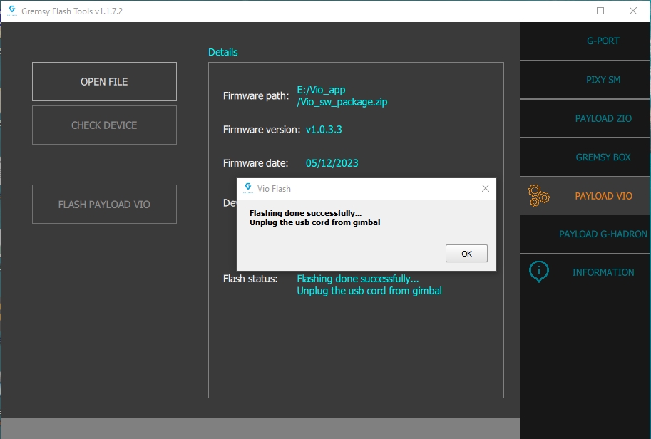
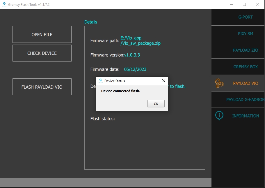
Open the firmware package, Please open the zip file and do not unzip.
Checking the connection between GremsyFlashTools app and the Vio/Zio payloads.
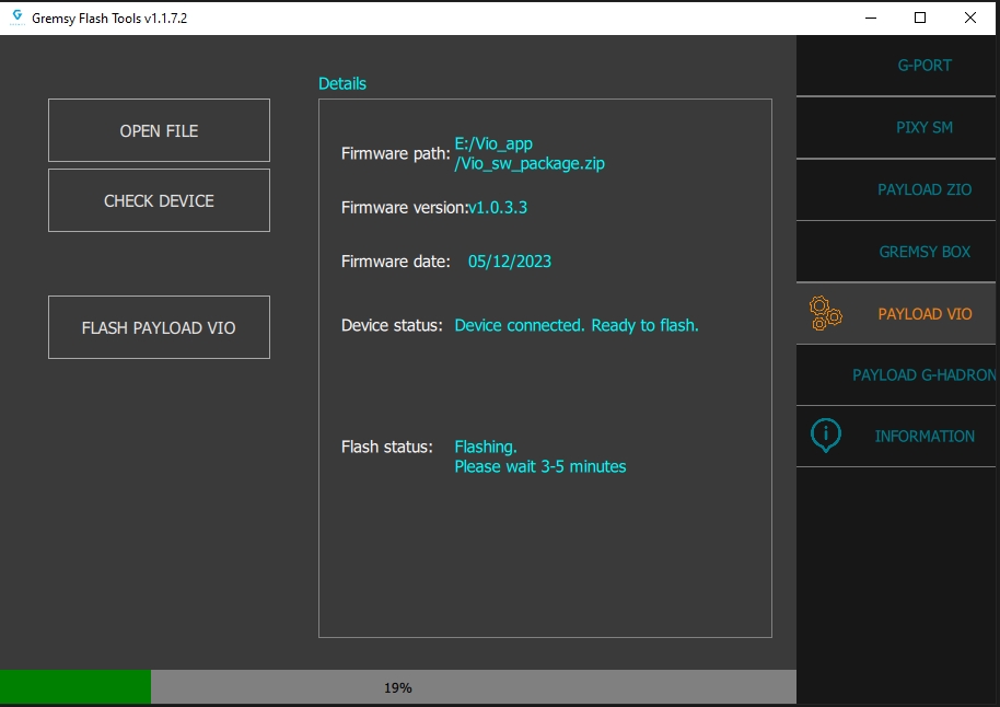
Waiting for the updating process to finish.
Flash Success.
Connect via UART
Controlled via Mission Planner or QGroundControl
Gimbal responds to waypoint missions and ROI commands
Ideally for Flight controller with onboard computing buit-in such as Skynode, VOXL2 (Jetson, RPi, NUC).
Use Ethernet for control (UDP) and video (RTSP)
Integrate using Gremsy Payload SDK for custom logic (optional)
Optional MAVLink passthrough to flight controller
Used in ground robots or special payload systems with/without flight controller.
Full control and video via Ethernet
Custom logic handled by onboard PC using Gremsy SDK
Click on “APPLY” to save the information.
Connect the USB Type-C port (located at the bottom of the Orus-L) to your computer using a USB cable.
The host computer will detect a new network adapter.
Orus-L will assign a DHCP IP address in the 192.168.55.x range to the host computer. Typically, the computer will receive the IP address 192.168.55.100.
Verify the connection by opening a terminal or command prompt and executing:
Open a web browser and navigate to the Orus-L settings interface:
Go to the IP Address tab, then enter your desired static IP address.
Click Apply and Reboot to restart the Orus-L and apply the new static IP settings.
If you have already changed the IP address and connected the Orus-L to your system using an Ethernet cable, follow the steps below to access and reconfigure the device.
Connect Orus-L via Ethernet
Plug an Ethernet cable into the Orus-L Ethernet port and connect it to your computer or network switch.
Access the Web Interface
In your browser, enter the updated IP address assigned to Orus-L using the following format:
Navigate to Static IP Settings
Once connected to the web interface:
Go to the IP Address tab.
Enter a new static IP address if needed.
Apply the Changes
Click Apply and Reboot to save the new configuration. The Orus-L will restart with the updated IP settings.
✅ Tip: Make sure your computer is in the same subnet (e.g., 192.168.55.x) to maintain connectivity.
Click “UPDATE” to begin the upgrade process.
The process will take about 2 minutes.
When the firmware is upgraded successfully, click "OK", the gimbal will be restarted automatically.
⚠️ Do not power off or disconnect the device during the update.
Enable or disable the automatic speed adjustment feature for gimbal movements.
Enable – Gimbal movement speed adjusts dynamically based on input
Disable – Gimbal speed remains constant, as defined by user input settings
Firmware updates take effect after the update process completes. Changes to Gimbal Control settings apply immediately after clicking “UPDATE”.
STEP 1: The marks on the top part and bottom part must be aligned. The button on the ring should be aligned with the unlocked icon as shown in the first picture.
STEP 2: Keep everything aligned and attach the bottom part to the top part.
STEP 3: Rotate the ring clockwise until the button on the ring aligns with the locked icon.
STEP 1: Press and hold the button, and rotate the ring counterclockwise.
STEP 2: When the button on the ring is aligned with the unlock icon, the ORUS L can be detached from the top part of the Quick Release.


Your PC will automatically display a notification:
L4T-README (E:)
💡 This confirms that the device is recognized.
Gimbal rotation control channel: CH6 (or any channels), use the wheel button on the Herelink remote:
Gimbal axis selection channel: CH8 (or any channels), use the camera button on the Herelink remote.
Successful connection


Specifications are subject to change. Product currently in release phase.
Input range: 19-52 VDC
Connector type: JST SM02B-SFKH-TF
Use to output video from the camera
Connector type: HDMI micro
Connector Type: BM05B-GHS-TBT
Pinout:
LAN_TX_P
LAN_TX_N
LAN_RX_P
LAN_RX_N
Connector Type: BM09B-GHS-TBT
Pinout:
5V
SBUS/PPM
GND
SPEK (JR)
Supported cable not include on the package
Connector Type: BM07B-GHS-TBT
Pinout:
RESERVE
RESERVE
MAVLINK_RX
MAVLINK_TX
USB Ethernet to configure the ORUS L settings via web app and upgrade software
To reset the computer processor inside ORUS L
Connector type 1: Housing 3 2.54mm
Connector type 2: GHR-09V-S
Connector type 1: GHR-05V-S
Connector type 2: RJ45
Connector type 1: GHR-05V-S
Connector type 2: GHR-05V-S
Connector type 1: GHR-07V-S
Connector type 2: GHR-06V-S
The information about UPGRADE FIRMWARE for ZIO PAYLOADS and VIO PAYLOADS.
Step 1: Before the upgrade
Download the latest Software version for MAC or Windows if not installed yet.
Unplug the Remote Receiver (SBUS, JR, …) if it was plugged into the gStabi system.
Power on the gimbal.
Connect Gimbal to your Mac or PC by USB cable.
Step 2: Upgrade firmware
Run the gTune Desktop software.
Click on the “Connect” button.
Go to “UPGRADE” -> "UPGRADE FIRMWARE" tab.
Click "AUTO UPGRADE"
Make sure the RF receiver (if available) is already removed.
Select Gimbal firmware version to upgrade
Click “Upgrade” button. The process will take about 2 minutes. When the firmware is upgraded successfully, click "DONE", the gimbal will be restarted automatically.
Step 1: Before the upgrade
Download the latest Software version for MAC or Windows if not installed yet.
Unplug the Remote Receiver (SBUS, JR, …) if it was plugged into the gStabi system.
Power on the gimbal.
Connect Gimbal to your Mac or PC by USB cable.
Step 2: Upgrade firmware
Run the gTune Desktop software.
Click on the “Connect” button.
Go to “UPGRADE” -> "UPGRADE FIRMWARE" tab.
Click "MANUAL UPGRADE"
BROWSE” to firmware file from your computer.
Disconnect any RC or COM port that are being connect with gimbal before upgrading.
Click “Upgrade” button. The process will take about 2 minutes. When the firmware is upgraded successfully, click "DONE", the gimbal will be restarted automatically.
Go to "Set Up Remote Channels" on the Webserver app
Params explaination
Control Mode:
Disable
Raw Input: Control Gremsy Payload by sbus from gimbal
Autopilot Convert: Control Gremsy Payload by sbus from autopilot
Image Capture: Select push button. Capture Image when pressing button
Notes: If the channels will not be use, please set it to "-1"
Setting App:
Select Disable in Control Mode
Set param Ardupilot:
Setting App:
Select Raw Input in Control Mode
Select the channel of the function to be controlled on App Setting
Select Raw Input in Control Mode
Set param Ardupilot:
BRD_SBUS_OUT: 50Hz (1)
Setting App:
Select Autopilot convert in Control Mode
Select the channel of the function to be controlled
Set param Ardupilot:
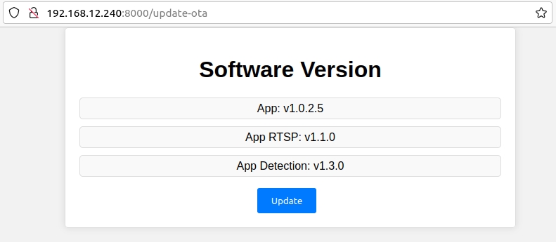
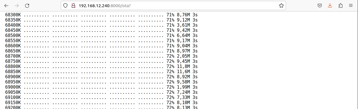
Process OTA Update Software for Zio Payloads and Vio Payloads.
This section will be used to do OTA software update for the Vio/Zio payload
The Vio payload support 2 ways to update their software: using GremsyFlashTools or using this feature
This feature will be connect to Gremsy server and download the latest software package.
The customer must make sure that the Vio/Zio payload was connected to the Internet before applying this feature.
Update Payload Software"The customer can see the current version of all apps in the Vio/Zio payload system before they deceide to do upgrade their Vio/Zio system.
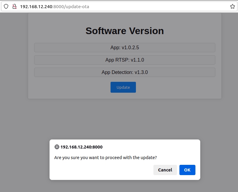
Update" the "OK" to perform this feature.The result of the OTA progress.
Note: do not turn off the power during the update process.
Setup Custom ModelsClick Apply to apply 2 models, COCO and CUSTOM for Payload Vio. The service will be restarted then checked for object detection.
The notification only pop up when the host PC is connecting to the Setting app via USB.
In this case, the Vio/Zio payload has 2 connection: USB to the host PC and Ethernet to the Internet router
The Settings app will send a notify to the user when this problem was detected.
Please check the Internet connection for the Vio/Zio payload.
If the Internet connection to the Vio/Zio payload was not stable, a notify will be pop up and the OTA progress will be canceled.
Please check the Internet connection for the Vio/Zio payload and try again
Please make sure the Vio/Zio payload will be not powered off while the OTA performing.
This section describes how to configure the storage and recording options for the Orus-L system.
Select the format in which infrared images will be saved:
JPEG – Standard image format
JPEG & CSV – Saves both the image and raw thermal data in CSV format
✅ Use “JPEG & CSV” if thermal analysis is required in post-processing.
Choose the video file format for recorded footage:
MP4 – Widely supported and efficient for general use
MKV – Supports more advanced features and metadata
Select the video encoding standard:
H.265 (HEVC) – Higher compression, smaller file sizes, ideal for longer recordings
H.264 (AVC) – Greater compatibility with legacy systems
📌 H.265 is recommended for modern workflows and efficient storage.
Electro-Optical (EO) Camera:
Choose the desired video quality based on your storage and performance needs:
20 Mbps (highest quality)
14 Mbps
8 Mbps
Infrared (IR) Camera:
Select from the following bitrate options:
4 Mbps
2 Mbps
1 Mbps
⚠️ Higher bitrates offer better image quality but use more storage.
Once all desired options are selected, click the “APPLY” button to save changes. The new configuration will take effect immediately or after a system restart, depending on the setting.
Control Mode:
Disable.
Raw Input: Control Zio Payload by SBUS from gimbal.
Autopilot Convert: Control Zio Payload by SBUS from autopilot.
Image Capture: Select push button. Capture Image when pressing button.
Video record: Select push button. Pressing the first time will start record video, pressing the next time will stop recording video.
Zooming: Select stick with 3 states. 3 states: zoom tele, stop zoom, zoom wide.
Tilt: Select rotate button. Control tilt axis.
Roll: currently not in use.
Pan: Select rotate button. Control tilt axis.
Mode: Select stick with 3 states. 3 states correspond to 3 gimbal mode: OFF, LOCK, FOLLOW.
Return Home: Select push button. Gimbal returns home when press button.
ZIO PAYLOADS
Gimbal Firmware
Gremsy Zio Firmware Latest version
What's new? - Add window dead zone in follow mode (only available when turn off REDUCE DIFT by DRONE PAN AXIS) - Limit rotation control with max window value (angle) - Compatible with Zio_Software Payload Firmware
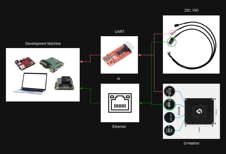
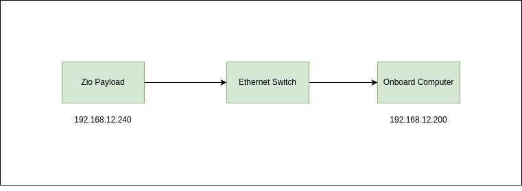
Simple Diagram to show how to connect the ZIO Payload via the Ethernet
This section allows users to manage stored media files directly from the Orus-L interface.
Options to manage captured infrared and electro-optical images:
Download All – Download all stored images to the host computer
Delete All – Permanently remove all stored images from internal storage
Options to manage recorded video files:
Download All – Download all recorded videos
Delete All – Permanently delete all stored video files
⚠️ Caution: Deleting media is irreversible. Ensure backups are made before selecting "Delete All."
Designed for developers and integrators, the Gremsy Payload SDK provides the tools you need to customize and control your Gremsy Payload and Gimbal system for unique applications.
https://github.com/Gremsy/PayloadSdk/tree/payloadsdk_v2
Ubuntu PC (x86_64)
Jetson platform (aarch64)
Raspberry Pi
PayloadSDK supports 2 control conections, that's configured at payloadsdk.h:
Figure 1: Hardware setup use Ethernet or UART connection
Install required lib
Build project
Zio is compatible with the Remote Control (RC) that supports the QGroundControl app (QGC). In this manual, all settings are made on the Herelink Remote Control, the other controller does the same.
Zio needs to set up two channels to control the gimbal: one channel is for controlling rotation, and the other is for choosing the controlling axis.
Gimbal rotation control channel: CH6 (or any channels), use the wheel button on the Herelink remote:
Gimbal axis selection channel: CH8 (or any channels), use the camera button on the Herelink remote:
Zio connects to FC at the baud rate of 115200. In case of connecting Zio to FC at any telemetry, note the telemetry setting at the corresponding baud rate. Example for telemetry 2:
Set mount params
Set RC map channels
Updating...
General diagram of the VIO Support page, and the steps you must go through to set it up properly. Please consult before going into details
The Zio payload will be shipped with default IP address is: 192.168.12.240
There are two ways to setting an IP address for the Zio payload:
Power off Zio payload
Create payload_setup.txt file in SDcard with your required IP address:
Plugin SDcard to Zio payload and power on Zio payload
NOTE: After rebooting Zio Payload,
payload_setup.txtfile in SDcard will be moved to the Zio payload and the file will be lost.
If you don't know Zio address, you can set IP address via SDcard (Tte section 1.1)
Using the web browser to open the Zio payload Setting app, with the url http://<zio_ip>:8000 (example: http://192.168.12.207:8000)
Open tab "Set Up Static IP Address" then input your required IP address
Click "Apply" and "OK" to reboot the Zio system to apply the new IP address.
Integration Capabilities
Gremsy payloads support standard communication protocols to interface smoothly with Pixhawk systems, including:
MAVLink v2 Protocol: Compatible with popular firmware such as PX4 and ArduPilot. The payload can receive and respond to gimbal control commands from the autopilot, including angle control, ROI (Region of Interest) tracking, and camera navigation along waypoints.
UART/Serial Communication: Gremsy gimbals offer UART ports for direct communication with the flight controller. Baud rate and protocol settings can be configured to match the specific autopilot setup.
Ethernet Interface: Enables high-speed, low-latency communication for advanced use cases:
UDP Protocol for real-time gimbal and camera control commands from onboard computers or ground stations.
RTSP (Real-Time Streaming Protocol) for live video streaming from the payload camera to ground control software or network video recorders.
Flight Stack without onboard computer E.g: Cube Pilot, Pixhawk series with Herelink v1.1 remote
Flight Stack with onboard computer built-in E.g: Skynode, VOXL2 with Herelink v1.1
Version: update to the latest version.
Support Mavlink v2 protocol
Zio connects to FC at the baud rate of 115200. In case of connecting Zio to FC at any telemetry, note the telemetry setting at the corresponding baud rate. Example for telemetry 2:
MAV_1_CONFIG: “TELEM 2”
SER_TEL2_BAUD: “115200 8N1"
MAV_1_FORWARD: "1"
MNT_MODE_IN: “RC”
MNT_MODE_OUT: “Unknown: 2”
MNT_RC_IN_MODE: “1”
MNT_MAN_PITCH: “AUX3” // PAN/TILT choose axis
RC_MAP_AUX1: “Channel 6” // set channel 6 to AUX1 (Yaw)
RC_MAP_AUX2: “Channel 7” // set channel 7 to AUX2 (Roll)
RC_MAP_AUX3: “Channel 8” // set channel 8 to AUX3 (Pitch)
In an increasingly complex and challenging world, Grempsy introduces a groundbreaking solution: the ORUS Large (ORUS L) – more than just a payload, it's the key to expanding vision and shaping the future. Our mission is to provide the most advanced surveillance and analysis tools, empowering our clients to make informed decisions in all conditions, even the most demanding. With ORUS L, you can see the unseen, master every challenge, and turn potential risks into competitive advantages. ORUS L: The ultimate payload solution for every mission, delivering safety, efficiency, and success.
Rugged Design, Endurance-Ready
1. System Overview Diagram
2. Hardware Connection
Option A: Ethernet (Recommended)
Connect Orus L's Ethernet port to the onboard computer's Ethernet port (or via USB-C to Ethernet adapter)
Option B: UART (Alternative)
http://<orus_ip>:80004 Mbps2 Mbps
1 Mbps (lowest quality)
MNT_MAN_ROLL: “AUX2” // Zooming, High: Zoom in, Neutral: Stop, Low: Zoom out (current: only using mode control by angle)
MNT_MAN_YAW: “AUX1” // PAN/TILT move
COM_RC_IN_MODE: “Unknown: 3”


Aerodynamic spherical form factor engineered for flight stability up to 100 km/h, ideal for fixed-wing and VTOL UAVs.
Optimize lightweight, compact construction ensures compatibility with endurance-focused platforms.
IP55-rated housing protects against dust and rain—ready for harsh field conditions.
Jetson Orin Onboard for Edge AI Processing
Built-in NVIDIA Jetson Orin module, delivering AI compute performance up to 100 TOPS
Enables real-time target detection, tracking, sensor fusion, and deep learning inference on the fly
Offloads heavy processing from the ground station or flight controller—ideal for autonomous operations
Open for third-party software involvement.
High-Precision Multi-Sensor Payload
EO Camera:
30x optical zoom, 4K resolution
Night vision support for low-light operations
IR Thermal Camera:
Radiometric 640×512 resolution with Blue UAS version powered by Flir Thermal Sensor
Accurate thermal inspection for infrastructure, energy, and emergency response
LRF – Laser Range Finder:
Long-range measurement up to 2400m
Enables precise ranging, target cordinate terrain profiling, and geo-referenced targeting
Sensor Fusion:
Real-time overlay of EO/IR/LRF data
Enables advanced perception, situational awareness, and tracking accuracy
Integrated AI & Tracking Capabilities
Developed by Gremsy, onboard algorithms include:
Automatic object tracking and detection
Target lock & follow
Scene understanding & adaptive behavior
Works fully onboard without constant connection to GCS
Flexible Integration & Developer Support
Ethernet (UDP) for real-time control
Ethernet RTSP for live video streaming (EO + IR)
UART/MAVLink for autopilot integration (PX4/ArduPilot)
Gremsy Payload SDK v3 for custom control, automation, and sensor coordination
Gremsy Payload Plus for field setup and mobile operations
Powerline, wind turbine, and pipeline inspection
Public safety & ISR mission.
Oil & gas and refinery monitoring
Border patrol, search and rescue, and thermal surveillance
UGVs and mobile robotics in infrastructure diagnostics

Photos: 3840x2160 - JPEG
Videos: 3840x2160, 30fps - MP4
The USB-C port is used for upgrading the firmware of the camera.
Zio will be used with the latest Gremsy Quick Release - Zio Quick Release, which will help users can plug and unplug the camera in or out of the drone as fast as possible.
It does not support but we will provide the specification of the hole in front of the camera so you can customize it.
The Zio has 2 types of zoom: 20 times optical zoom with an additional 12 times digital zoom.
The optimization zoom is 30x in super-resolution zoom mode.
The maximum zoom is 240x when combined with 20 times optical and 12 times digital zoom.
Zio must first pass rigorous testing in accordance with Gremsy's quality standards before reaching the user.
Zio is dustproof to the IP5x standard.
Make sure the gimbal is securely installed on the aircraft and the SD card slot cover is clean and closed properly.
Make sure the surface of the gimbal is clean before opening the SD card slot cover.
The Zio is mainly designed for inspection and surveying over long distances, thanks to 30x zoom and 4K video resolution capacity.
It's can be mounted on DJI drones having a suitable size but does not support the control
The Zio only supports drones using the Mavlink base.
Yes, you can use 2 Herelink remotes to control independently the drone and the gimbal.
You can refer to the instruction in this part.
It supports up to 64 GB capacity, and it is recommended to use a UHS-I Speed Grade 3 microSD card.
Currently, it is only compatible with the latest Android version of QGroundControl.


GND
3V3
CAN_L
CAN_H
GIMBAL_TX4
GIMBAL_RX4
GND
RESERVE
RESERVE


ping 192.168.55.1http://192.168.55.1:8000/*PAYLOAD CONFIGURATION*/
# IP address of Payload
ZIO_ADDR = 192.168.12.207
NETMASK = 255.255.255.0
GATEWAY = 192.168.12.1Zooming: Select stick with 3 states. 3 states: zoom tele, stop zoom, zoom wide
Tilt: Select rotate button. Control tilt axis
Roll: currently not in use.
Pan: Select rotate button. Control Pan axis
Mode: Select stick with 3 states. 3 states corresponding to 3 gimbal mode: OFF, LOCK, FOLLOW
Return Home: Select push button. Gimbal return home when press button
RC7_OPTION: “212”
RC8_OPTION: “213”
RCx_OPTION: 0
SERVOx_FUNTION: RCINx
x is the channel number you want to Sbus out
Ex: RC6_OPTION: 0, SERVO6_FUNTION: RCIN6 --> Sbus out channel 6
SR2_RC_CHAN: 10Hz
Ensure proper logic level (3.3V TTL)
Optional:
Connect Flight Controller (Pixhawk) via separate UART for MAVLink passthrough if needed
3. Software Setup: Gremsy Payload SDK (v3)
A. Install SDK (Python version)
B. Initialize SDK and Connect
C. Send Basic Commands
4. RTSP Video Streaming
Use VLC or OpenCV to access the video stream:
Example with OpenCV:
5. Optional: Integration with MAVLink and Flight Controller
If a flight controller is present, you can:
Forward MAVLink commands from Pixhawk to Orus L (mount_control)
Synchronize gimbal with autopilot commands
Requires proper UART bridge and time sync if needed
6. Use Cases
Onboard AI/ML target detection and autonomous gimbal pointing
GPS-denied or tethered drone operations
Ground robot (UGV) with 3-axis PTZ camera functionality
Inspection and defect detection robots with onboard processing
DETAILED PAYLOAD SDK
Video guide link here
Step 1: Swipe down from the top of the screen and enable WiFi.
Step 2: Hold press on Wifi's icon and login to Wifi


Power on ZIO
Plug-in USB-C cable on the camera side.
Press Reset button
GremsyFlashTools app supports update with file ".zip" and ".7z"
Download file zip file
After downloading the zip file, extract this file and make sure that The Firmware folder includes two files “setting.json” and “upgrade.7z”. These files must be in the same folder
NOTE:
Do not save the folder on Network Drive
Do not rename the folder or files. If you want to move the files to another place, copy the whole folder.
The firmware folder link must not have space (blank) or special characters. Ex: link on the picture above.
Plug-out USB-C from the payload
Reset the power or press the Reset button
This problem will be fixed when saving the folder where the path has no spaces or special characters.
Example: C:\Users\Admin\Desktop\PixySM300_SoM_Firmware\Pixy_SM_v2.1.0.38 (no spaces and special characters)
This error will be fixed by extracting the firmware again and not moving the files contained in the folder after decompression.
During the loading process, if there are other errors, please capture the error code and contact our support team by email: [email protected]
Go to "Set Up Remote Channels" on the Webserver app.
Params explanation:
Control Mode:
Disable.
Raw Input: Control Zio Payload by SBUS from gimbal.
Autopilot Convert: Control Zio Payload by SBUS from autopilot.
Image Capture: Select push button. Capture Image when pressing button.
Video record: Select push button. Pressing the first time will start record video, pressing the next time will stop record video.
Zooming: Select stick with 3 states. 3 states: zoom tele, stop zoom, zoom wide.
Tilt: Select rotate button. Control tilt axis.
Roll: currently not in use.
Pan: Select rotate button. Control tilt axis.
Mode: Select stick with 3 states. 3 states corresponding to 3 gimbal mode: OFF, LOCK, FOLLOW.
Return Home: Select push button. Gimbal return home when press button.
Notes: If the channels will not be used, please set it to "-1".
Setting App: Select Disable in Control Mode
Set param Ardupilot:
RC6_OPTION: “214”
Setting App:
Select Raw Input in Control Mode
Select the channel of the function to be controlled on App Setting.
Select Raw Input in Control Mode
Set param Ardupilot:
BRD_SBUS_OUT: 50Hz (1)
X is the channel number you want to SBUS out
For Example: RC6_OPTION: 0, SERVO6_FUNTION: RCIN6 --> SBUS out channel 6.
Setting App:
Select Autopilot convert in Control Mode
Select the channel of the function to be controlled
Set param Ardupilot:
Version: Ardupilot 4.3 or higher
Support Mavlink v2 protocol
Zio connects to FC at the baud rate of 115200. In case of connecting Zio to FC at any telemetry, note the telemetry setting at the corresponding baud rate. Example for telemetry 2:
SERIAL2_PROTOCOL: “Mavlink2”
SERIAL2_BAUD: “115200”
RC6_OPTION: “214” // PAN/TILT move
RC7_OPTION: “212” // Zooming, High: Zoom in, Neutral: Stop, Low: Zoom out
RC8_OPTION: “213” // PAN/TILT choose axis
MNT1_DEFLT_MODE: "3"
RC6_OPTION: “0”
RC7_OPTION: “0”
RC8_OPTION: “0”
MNT_RC_IN_PAN: “6” // PAN/TILT move
SR2_POSITION: "10" // receive GPS messages
SR2_EXT_STAT: "2" // receive GPS lock signal
CAN_P1_DRIVER: "1" (First drive) // enable CAN1 port
CAN_P2_DRIVER: "1" (First drive) // enable CAN1 port
GPS_TYPE: "9" (UAVCAN)
NTF_LED_TYPES: "231"
Companion / Onboard Computer (Jetson / RPi / NUC)
├── [UDP via Ethernet or UART] → Orus L Control (Payload SDK)
├── [RTSP Stream] ← Orus L Camera Output
└── [Optional] → Flight Controller (MAVLink)# Clone the SDK
git clone -b payloadsdk_v3 https://github.com/Gremsy/PayloadSdk.git
cd PayloadSdk/python
# Install dependencies
pip install -r requirements.txtfrom payloadsdk import GremsySDK
# Create SDK instance and connect via Ethernet (UDP)
sdk = GremsySDK(protocol='udp', target_ip='192.168.12.249', target_port=14566)
# Or connect via UART
# sdk = GremsySDK(protocol='serial', serial_port='/dev/ttyUSB0', baudrate=115200)
sdk.connect()# Move gimbal to specific angles
sdk.gimbal_control.set_angle(pitch=0.0, roll=0.0, yaw=90.0)
# Start/Stop video recording
sdk.camera_control.set_recording(True)
# Set gimbal mode
sdk.gimbal_control.set_mode('lock')rtsp://192.168.12.249:8554/payloadimport cv2
cap = cv2.VideoCapture('rtsp://192.168.12.249:8554/payload')
while True:
ret, frame = cap.read()
if ret:
cv2.imshow("Orus L Stream", frame)
if cv2.waitKey(1) == 27:
break
cap.release()
cv2.destroyAllWindows()git clone -b develop --recurse-submodules https://github.com/Gremsy/PayloadSdk.git
cd PayloadSdk/libs/gSDK/
git checkout gSDK_V3_alpha
git pull origin gSDK_V3_alphasudo apt-get install libcurl4-openssl-dev libjsoncpp-devcd PayloadSdk
mkdir build && cd build
cmake -Dpayload ../
e.g. cmake -DVIO=1 ../
cmake -DGHADRON=1 ../
cmake -DZIO=1 ../
make -j6MAV_1_CONFIG: “TELEM 2”
MAV_2_CONFIG: "EXT2" (401)
MAV_2_MODE: "Gimbal" (10)
SER_TEL2_BAUD: “115200 8N1"
SER_EXT2_BAUD: “115200 8N1"
MAV_2_FORWARD: "enable" (1)
MAV_S_FORWARD: "enable" (1)MNT_MODE_IN: “RC”
MNT_MODE_OUT: “MAVlink gimbal protocol v2”
MNT_RC_IN_MODE: “1”
MNT_MAN_PITCH: “AUX3”
MNT_MAN_ROLL: “AUX2”
MNT_MAN_YAW: “AUX1”
MNT_RATE_PITCH: "90"
MNT_RATE_YAW: "90"RC_MAP_AUX1: “Channel 6”
RC_MAP_AUX2: “Channel 7”
RC_MAP_AUX3: “Channel 8”MNT1_TYPE: “6”
MNT1_RC_RATE: “240” // change control gimbal by speed
CAM_TYPE: "6"
MNT_RC_IN_ROLL: “7” // Zooming, High: Zoom in, Neutral: Stop, Low: Zoom out
MNT_RC_IN_TILT: “8” // PAN/TILT choose axis
MNT_TYPE: “SToRM32 MAVLINK"
5
MNT_RANGE_YAW
720.0 deg
6
MNT_RATE_PITCH
720.0 deg
7
MNT_RATE_YAW
720.0 deg
8
MNT_MAN_PITCH
AUX2
9
MNT_MAN_YAW
AUX3
10
MNT_MODE_IN
Auto (RC and MAVLink gimbal Protocol V2)
11
MNT_MODE_OUT
MAVLink gimbal protocol V2
MAV_0_CONFIG
Disabled
2
MAV_1_CONFIG
TELEM 2
3
MAV_2_CONFIG
EXT2
4
MAV_2_FORWARD
Enabled
5
MAV_2_MODE
Gimbal
6
MAV_2_RATE
92160 B/s
7
MAV_S_FORWARD
Enabled
8
MAV_TYPE
Hexarotor
1
MNT_MODE_IN
Auto (RC and MAVLink gimbal Protocol V2)
2
MNT_MODE_OUT
MAVLink gimbal protocol V2
3
MNT_RANGE_PITCH
720.0 deg
4
MNT_RANGE_ROLL
720.0 deg


RC7_OPTION: “212”
RC8_OPTION: “213”
BRD_SAFETY_MASK: 0 (Uncheck channel control)
RCx_OPTION: 0
SERVOx_FUNTION: RCINx
SR2_RC_CHAN: 10Hz


This section allows you to configure environmental parameters to improve the accuracy of thermal measurements based on real-world conditions.
Range: 100 to 500 Kelvin Set the ambient air temperature for thermal compensation.
Range: 0 to 255 meters Enter the distance between the Orus-L and the target object to enhance thermal accuracy.
Range: 0% to 100% Defines the emissivity of the target surface.
⚠️ Default for most organic materials is around 95%.
Range: 0% to 100% Input the relative humidity of the environment, which may affect thermal readings.
Range: 0 to 255 (each) Advanced calibration parameters used for fine-tuning thermal correction models.
Only modify if you have specific calibration requirements or guidance.
Range: 100 to 500 Kelvin Temperature of the window or lens surface through which the sensor observes the target.
Choose your preferred unit for displaying temperature:
Celsius (°C)
Fahrenheit (°F)
Kelvin (K)
Click “APPLY” to save and activate the new environmental configuration. Settings will be used to refine thermal imaging calculations in real time.
This page will show you step by step to configure ZIO payload with Ardupilot system.
Important note
Gimbal firmware: v7.8.1 or higher.
Software: v2.0.1 or higher.
Plug the Sbus Remote into the Zio control cable
Connect gTune to Zio Payload
Go to SETTINGS -> CONTROLS -> SBUS.
Select YES to complete
Set IP Zio Payloa by SDcard
In SDcard create a file named payload_setup.txt
File content:
Set Remote Channels via Setting App
Plug Ethernet into the PC and connect to address: http://192.168.12.240:8000 to enter Setting App.
Select Set Up Remote Channels
Select Control Mode as Raw Input and fill in the following parameters:
Select Apply to complete.
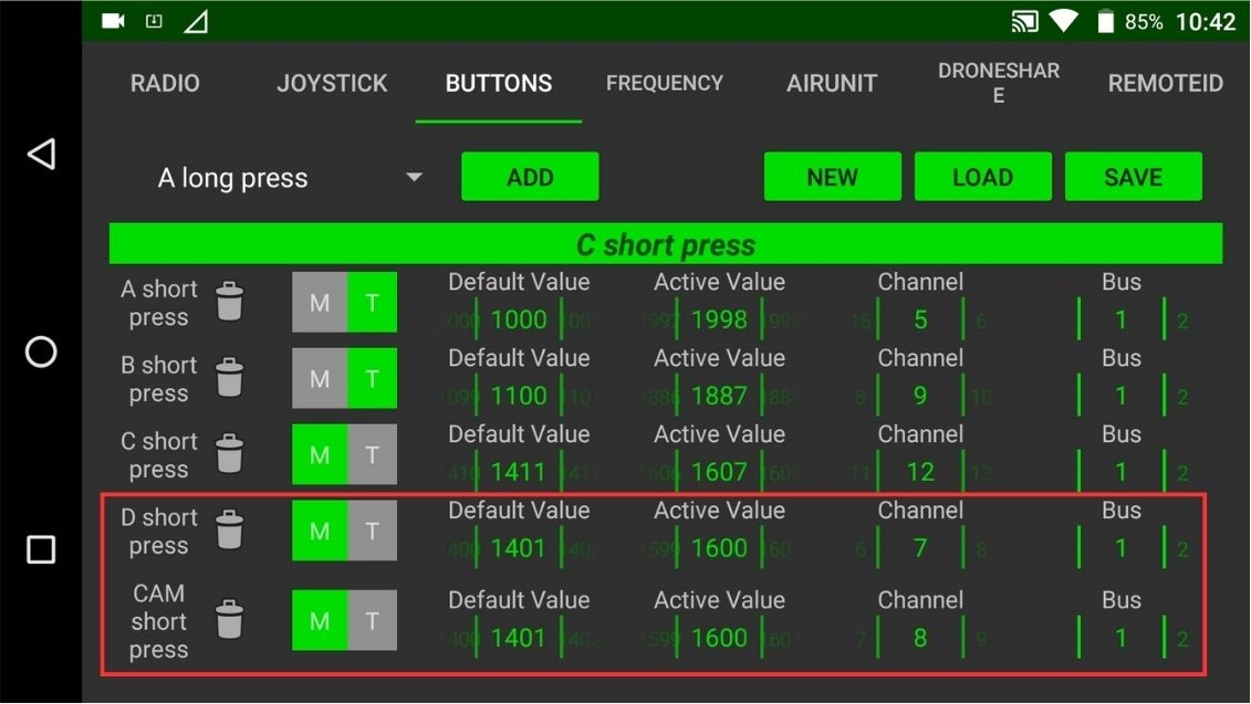
BUTTON FUNCTIONS:
Push the lever up and down to control the gimbal moving up and down (Tilt axis control).
Push the lever left-right to control the gimbal moving left to right (Pan axis control).
NOTE: To control the gimbal moving up and down back and forth (Tilt, Pan), complete this step.
Stick Gimbal Mode has 3 states (top, middle, bottom)
Stick top: Gimbal is in lock state (gimbal light is on, flashing light).
Stick middle: Gimbal is in follow state (gimbal light is bright, not flashing).
Stick below: Gimbal OFF (gimbal light is off, gimbal is off).
Push the lever up and down to operate
Gimbal returns to home position (starting position).
The initial position is to turn all the way to the left.
Turn the knob all the way to the right and then turn it back to the original position to take a photo.
Select
List Fileson the Setting App to check if there is an image file after taking a photo (each time take a photo, reload the website).
The initial position is to turn all the way to the left.
Turn the knob all the way to the right and then turn it back to the start to Record Video.
Wait about 5 seconds then repeat as above to finish Record Video.
When you start Recording Video, the Payload light will change from green to blue
When Record Video finishes, the Payload light will turn back to green
Go to
List Fileson Setting App to check if there is a video file after Recording Video(each time Recording is finished, reload the website).
Stick Zoom has 3 states (top, middle, bottom)
Stick top: start to zoom forward.
Stick in the middle: Camera does not zoom.
Stick below: start to zoom back.
In SDcard create a file named payload_setup.txt
File content:
To receive essential positioning and status information:
SR2_POSITION = 10 → GPS Position
SR2_EXT_STAT = 2 → GPS Lock Status
If using a UAVCAN GPS unit:
CAN_P1_DRIVER = 1 → Enable CAN1
CAN_P2_DRIVER = 1 → Enable CAN2
GPS_TYPE = 9 → UAVCAN GPS
NTF_LED_TYPES = 231 → Enable Standard Notification LEDs
Allow turn on/off the Auto Object Detection function of Zio.
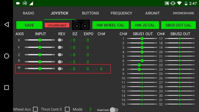
Payload control by remote.
There are 2 options:
Single Operation: controlled by a Herelink remote, Pan channel will be the speed value, Tilt channel will be the axis selection value (assigned to a button on the remote)
Dual Operation: controlled by 2 Herelink remotes (the main remote controls the drone, and the secondary remote controls the payload). The Pan channel controls the Pan axis, Tilt channel controls the Tilt axis.
Set “On Screen Display” mode.
OSD feature only overlays on the HDMI output, not on the Ethernet output.
There are 3 modes to choose from:
Disable: turn off the OSD feature, do not overlay on the screen.
Debug: display Debug parameters on the screen.
Status: display the operating parameters of the system on the screen.
Select module settings:
Camera Device: settings for the camera
Gimbal Device: settings for gimbal
Flip video output settings. There are 2 options: ON/OFF
Autosave
Set video output
There are 3 options:
HDMI 1080p60
Ethernet 1080p60
HDMI 1080p60 and Ethernet 720p60 simultaneously
Autosave
Set Defog mode for Sony Block There are 2 options: ON/OFF
Exposure settings for Sony Block
There are 5 options:
Full Auto (recommend)
Manual: mode can choose Shutter speed and Aperture manually
Shutter speed priority
Iris priority
Autosave
Set Shutter Value for Sony Block.
There are 10 options: 1/10 to 1/2000
5.6 Aperture Value
Set Shutter Value for Sony Block.
Set white balance mode for Sony Block
There are 6 options:
Auto (recommend)
Indoor
Outdoor
One Push WB (not available)
Autosave
Set Zio zoom mode There are 2 options:
Combine: this zoom mode is a combination of Optical and Digital, allowing a maximum zoom of 240x.
Super Resolution: special zoom mode from Sony, automatically analyzes and combine Optical and Digital zoom, ensuring the best image quality. allows up to 30x. zoom.
Set the Zoom level for the camera
With Combine mode. these are 7 options: 1x to 240x
With Super Resolution mode. these are 16 options: 1x to 30x
Autosave
Set Focus Mode for Sony Block There are 4 options:
Manual
Auto Zoom trigger: regain focus every time the Zoom level is changed
Auto Focus Near: automatically focus on close
Auto Focus Far: automatically focus far away
Autosave
Set gimbal mode
There are 3 options:
Off
Lock
Follow
Set gimbal control speed split when Zio Payload is zooming.
There are 2 options: Disable/Enable
NOTE: Gimbal Combine Zoom only works when using PayloadSDK
To use the "Dual operation" mode, two Herelink remotes need to be connected to the same network. Specifically:
The main remote will broadcast Wi-Fi
The Slave remote will connect to the main's Wi-Fi
The main remote is a remote directly connected to Air Unit
Turn on “Dual Cont” and “Main”
Choose “Save” and restart the remote
The Slave remote is a remote that will connect to the system via the Wi-Fi of the Main remote
Step 1: Connect to the Wi-Fi of the main remote
Step 2: Install Dual Operation mode
Turn on “Dual Cont” and choose IP target is the IP of the Main remote (default: 192.168.43.1)
Choose “Save” and restart the remote
Step 3: Set app QGroundControl
Turn off all options in AutoConnection
Create the UDP connection to the main remote
The menu for controlling the payload after a successful connection.
Setup receive video sharing
After setting both main and slave remote in "Dual Cont" mode, the joystick channels of the slave remote will display the value on the main remote.
User can choose joystick to control payload
Set corresponding channel: CH6 for pan, CH8 for tilt (or change axis in single mode)
Choose the Dual Operation on the RC Mode - Camera Settings Menu
Successful connection
Welcome to the Gremsy Payload Support page, your one-stop destination for expert assistance with Gremsy's cutting-edge payload solutions. Whether you’re integrating our advanced payload systems into your projects or need troubleshooting guidance, our dedicated support team is here to ensure optimal performance and seamless operation.
On this page, you’ll find detailed product manuals, firmware updates, and FAQs tailored to address common inquiries. For personalized support, connect with our support team via [email protected] who can provide step-by-step assistance, helping you get the most out of your Gremsy products. We're committed to your success and are here to support you every step of the way.
/*PAYLOAD CONFIGURATION*/
# IP address of Payload
ZIO_ADDR = 192.168.11.240
NETMASK = 255.255.255.0
GATEWAY = 192.168.12.1/*PAYLOAD CONFIGURATION*/
# IP address of Payload
ZIO_ADDR = 192.168.12.240
NETMASK = 255.255.255.0
GATEWAY = 192.168.12.1


Bright
ATW (not available)
Manual (not available)


ORUS-L
VIO
ZIO


213
z is desired channel match with remote/ground station button (joystick)
Standard mode: TILT control
Gremsy mode: Select axis: PAN or TILT
Mount Settings
MNT1_TYPE
6
MAVLink Gimbal Type
Mount Settings
MNT1_DEFLT_MODE
3
Default to RC Targeting mode
Mount Settings
MNT1_RC_RATE
240
Speed control rate for gimbal
Camera Settings
CAM_TYPE
6
MAVLink Camera integration
RC Channel Options
RC7_OPTION
0
Disabled
RC Channel Options
RC8_OPTION
0
Disabled
Mount RC Mapping
MNT_RC_IN_PAN
6
PAN/TILT move (assigned to RC channel 6)
Mount RC Mapping
MNT_RC_IN_ROLL
7
Zoom control (High = Zoom In, Neutral = Stop, Low = Zoom Out)
Mount RC Mapping
MNT_RC_IN_TILT
8
Axis select (assigned to RC channel 8)
Mount Settings
MNT_TYPE
4 (SToRM32 MAVLINK)
Set gimbal mount type to SToRM32 MAVLink
Telemetry Setup
SERIAL2_PROTOCOL
2
Use MAVLink2 protocol
Telemetry Setup
SERIAL2_BAUD
115
Set baud rate to 115200
RC Channel Options
RCx_OPTION
214
x is desired channel match with remote/ground station button (joystick)
Standard mode: PAN control
Gremsy mode:PAN/TILT move (speed-based control)
RC Channel Options
RCy_OPTION
212
y is desired channel match with remote/ground station button (joystick)
Standard mode: Roll control
Gremsy mode: not applicable
RC Channel Options
Telemetry Setup
SERIAL2_PROTOCOL
2
Use MAVLink v2 protocol on Telemetry 2
Telemetry Setup
SERIAL2_BAUD
115 (115200)
Set telemetry baud rate to 115200
RC Channel Options
RC6_OPTION
0
RCz_OPTION
Disabled
File name: payload_setup.txt
File Content:
On the above example:
Zio IP: 192.168.144.200
Zio stream video to the IP: 192.168.144.104 at port 5000 -> we not use video streaming via ethernet
NOTE: when Zio starts up without detecting the file payload_setup.txt in the memory card, Zio will automatically reset to the default IP (192.168.50.100)
File Name: zio_herelink_eth.conf
File Content: (Copy exactly below)
NOTE:: After adding two files "payload_setup.txt" and "zio_herelink_eth.conf" to micro SDcard, please reboot the Zio to apply changes.
2.1 Disable all AutoConnect in General.
2.2 Navigate to Comm Links, add new Comm link for Ethernet telemetry
2.3 Create the new link as following
On the above example:
Connect the HDMI to Herelink v1.1
Video Stream info will show as below after configuring successfully
(Do not change)
Successful connection
Zio will be used with the S-PORT, which will help users plug and unplug the camera in or out of the drone as fast as possible.
Connector type: GHR-06V-S
Connector type: RJ45 CAT5R
Connector type: Futaba JR Male 2.54
Vio
The weight of the gimbal is 854G/ 1.88 LBS
EO Photo: 3840 x 2160 (8.51 MP). Video: 3840 x 2160 (4K@30fps).
IR Photo: 640×512 Video: 640×512 @ 60fps (VIO F1). Photo: 640×512 Video: 640×512 @ 30fps (VIO G1).
The USB-C port is used for upgrading the firmware of the camera.
Vio will be used with the latest Gremsy Quick Release - Vio Quick Release, which will help users can plug and unplug the camera in or out from the drone as fast as possible.
It does not support but we will provide the specification of the hole in front of the camera so you can customize it.
The Vio has 2 types of zoom:
EO Zoom: 20 times optical zoom with an additional 12 times digital zoom. The optimization zoom is 30x in super-resolution zoom mode. The maximum zoom is 240x when combined with 20 times optical and 12 times digital zoom.
IR Zoom: 1x to 8x zoom.
Vio must first pass rigorous testing in accordance with Gremsy's quality standards before reaching the user.
Vio is dustproof to the IP5x standard.
Make sure the gimbal is securely installed on the aircraft and the SD card slot cover is clean and closed properly.
Make sure the surface of the gimbal is clean before opening the SD card slot cover.
The Vio is mainly designed for inspection, surveying, thermal use over long distances, thanks to 30x zoom and 4K video resolution capacity.
It's can be mounted on DJI drones having a suitable size but does not support the control
The Vio only supports drones using the Mavlink base.
Yes, you can use two Herelink remotes to control independently the drone and the gimbal.
You can refer to the instruction in this
It supports up to 64 GB capacity, and it is recommended to use a UHS-I Speed Grade 3 microSD card.
Currently only compatible with the latest Android version of QGroundControl.
-> MP4 and mkv only, not in radiometric format yet.
-> Currently, Vio F1 does not support the capability to capture photos or videos in a radiometric format compatible with Flir software. We are collaborating with Flir to implement this functionality soon.
Presently, Vio F1's thermal camera is primarily for direct observation during flight rather than for thermal image analysis applications. We are actively pursuing updates to enhance its capabilities.
-> No, it's JPEG, not RJPEG.
-> No, we just provide SDK for the payload control and data transmision. Post processing will be on part of third party software or developer.
Yes, they can be capture simutaneously.
Yes, they can be streamed simutaneously.
-> Yes, and it already tagged including with the GPS on the EXIF file.
1Hz
Ardupilot 4.3 or higher
PX4 1.14 or higher
If you have any problem during integrate with newer version, please let us know via [email protected]
This section allows you to configure video streaming parameters for optimal performance based on your network conditions and operational requirements.
Determines whether the stream starts automatically when the system powers on:
Enable – Automatically initiates video streaming
Disable – Requires manual start.
Sets the data rate for video transmission. Higher bitrates offer better quality but require more bandwidth:
512 Kbps
1 Mbps
2 Mbps
4 Mbps
Defines the stream endpoint name used by RTSP clients (e.g., VLC, Payload Assitant App/Desktop):
Default: payload
You can change this value as needed for your streaming setup.
Specifies the port number used for RTSP streaming:
Default: 8554
📌 Ensure this port is open and not blocked by firewalls on your network.
Select the desired output resolution:
1920 × 1080 (Full HD)
1280 × 720 (HD)
640 × 360 (Low Bandwidth Mode)
Choose the video compression format:
H.264 (AVC) – Standard and widely supported
H.265 (HEVC) – Higher efficiency, reduced bandwidth usage
Set the number of video frames per second (FPS):
Range: 1 to 30 FPS
Lower frame rates reduce bandwidth and power consumption.
Enable or disable a separate infrared video stream:
Enable – Streams IR video independently from EO
Disable – IR is not streamed or is embedded with EO feed
Click “APPLY” to save and apply your selected streaming configuration. Streaming changes may take effect immediately or require a system reboot.
/*PAYLOAD CONFIGURATION*/
# IP address of Payload
ZIO_ADDR = 192.168.144.200
NETMASK = 255.255.255.0
# IP adress of UDP stream receiver
STREAM_VIDEO_TO = 192.168.144.104:5000# Herelink air-unit endpoint
# This endpoint will connect to Herelink air-unit
[UdpEndpoint Ethernet_MavIn_Herelink]
Mode = Normal
Address = 192.168.144.10
Port = 14552
Group = Mavlink_In
# Ground control station endpoint
# Please setup an UDP commlink on QGroundControl to this endpoint
[UdpEndpoint GCS_Ethernet_Endpoint]
Mode = Normal
Address = 192.168.144.11
Port = 14565
Group = Mavlink_OutName: Zio
Type: UDP
Listening Port: 14565
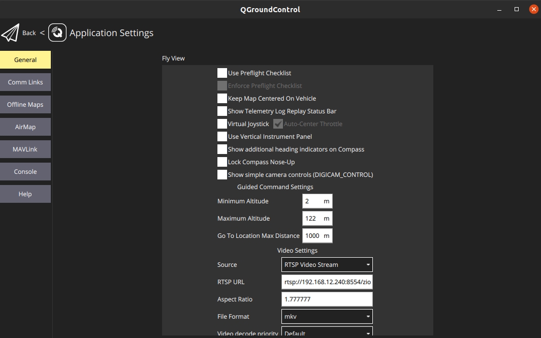
Target Hosts: 192.168.144.200:14565 (Zio's IP)Video Source: RTSP Video Stream
RTSP URL: rtsp://192.168.144.10:8554/H264Video
Aspect Ratio: 1.7777778 Mbps


x
x
5
x
x
6
Black
GND
x
x
5
x
x
6
Black
RX_N
7
x
x
7
x
x
1
x
x
2
Brown
Payload RX
3
Orange
Payload TX
1
Orange
TX_P
2
Brown
TX_N
3
Red
RX_P
1
Orange
SBUS Signal
2
Red
5V
3
Black
GND


4
4
⚪
White Solid
Initializing
3
⚪✨
White Blink
Calibrating
4
🟢✨
Green Blink
Gimbal Ready – Lock mode
5
🟢
Green Solid
Gimbal Ready – Follow mode
6
🔵✨
Blue Blink
Payload Ready* – Lock mode
7
🔵
Blue Solid
Payload Ready – Follow mode
8
🔴✨
Pink Blink
Payload connected system** with attitude input – Lock mode
9
🔴
Pink Solid
Payload connected system with attitude input
– Follow mode
1
🔴
Red
Payload Error
2
🟡
Yellow
Payload Power On
3
🟢
Green
1
🔴
Red Solid
Gimbal Error
2
Zio Payloads
Zio is a high-resolution zoom payload that combines a Sony sensor with high-stabilized three-axis gimbal technology. It enables industrial inspectors and surveyors to zoom into objects of interest and effortlessly transmit video at 4K resolution, ready to be utilized for a variety of different inspection, surveying, and public safety jobs.
Payload Ready to Work
4
🔵
Blue
Recording Video
Allen key 2mm
1
5
Allen key 2.5mm
1
6
M3 x 6 Hexagon Screw Bolt Cut Head
4
7
M3 x 6 Hexagon Screw Flat Head
4
8
USB Type A to USB Type C Cable
1
9
Micro USB Cable
1
10
Zio Control Cable
1
11
Zio Power Cable
2
12
Micro SD Card SDXC I, 64GB
1
32° F ~ 122° F (0° C ~ 50° C)
Operating Temperature
32° F ~ 122° F (0° C ~ 50° C)
Compatible Drones
Drone supported by PX4 and Ardupilot
Recommended FC: Cube
Photo: JPEG
Video: MP4
Defog mode
On/Off (Low, Mid, High)
White Balance
Auto, Indoor, Outdoor
Shutter Speed
1/30 to 1/2000s
Exposure mode
Auto, Shutter speed, Iris, Bright, Manual
Zoom mode
Combine, Separate, Super Resolution
Storage
MicroSDXC I (a 64GB SD card included)
1
Zio Payload
1
2
Zio Damping
1
3
Zio Quick Release
1
Payload Dimensions (DxWxH)
145mm × 90mm × 148mm
Weight
480g (1.06 lbs)
Input Voltage
14.5V - 52V
Power Consumption
12W-48W
Connections
USB 2.0, UART, Ethernet, Micro HDMI
Remote Software
QGroundControl
Streaming Video
HDMI output: 1080p60 (1920x1080 | 60fps)
Ethernet output: 720p60 (1280x720 | 30fps)
Video Bit Rate is adjustable
Angular Vibration Range
±0.01°
Gimbal Mount
Bottom mount (Detachable)
Controllable Range
Tilt: ±120°
Pan: ±320°
Mechanical Range
Tilt: +138° to -198°
Pan: ±335°
Roll: +75° to -265°
Max Controllable Speed
Tilt: 100°/s
Pan: 100°/s
Working Current:
Static current: 1.0A (@12V)
Dynamic current: 1.5A (@12V)
Locked motor current: Max 4.0A (@12V)
Sensor
1/2.5" Exmor R CMOS
Effective Pixels
8.51 MP
Zoom
Optical: 20x
Digital: 12x
Super Resolution: 30x
Combine: 240x (recommend for photography only)
Camera Lens
f/2.0 to f/3.8 (4.4 to 88.4mm Equivalent)
FOV
Wide: 72°
Telephoto: 4.1°
Resolution
Photo: 3840 x 2160
Video: 3840 x 2160 @ 30 fps | 1920 x 1080 @ 30fps
Aspect Ratio
Photo: 16:9


4
Storage Temperature
Format

Camera Mode
Photo, Video
Video
Options: Combine / Super Resolution / Combine Zoom / Super Resolution Zoom
Description: Camera zoom modes:
Combine Zoom: Combines optical and digital zoom to achieve high magnification while maintaining reasonable image quality.
Super Resolution Zoom:
Options: OFF / ON
Description: Vertically flips the camera image (180°). Useful if the camera is mounted upside down or to adjust the viewing angle.
Mode Options: OFF / ON
Description: Enables or disables defog function for haze, smoke, or fog.
Level Options: Lowest, Low, Mid, High
Description: Adjusts defog intensity. Useful in low-visibility conditions to improve image clarity.
Options: Full Auto / Manual / Shutter Priority / Iris Priority / Bright
Description: Exposure control modes:
Full Auto: Camera automatically adjusts all parameters.
Manual: User sets shutter, aperture, gain manually.
Range: 1/10 → 1/2000 s
Description: Shutter speed. 1/10 s for low-light, 1/2000 s for fast-moving subjects.
Range: F2.0 → F11
Description: Lens aperture. Lower F = more light, shallower depth of field; higher F = less light, deeper depth of field.
Range: 0 → 41
Description: Adjusts overall image brightness. Used to make images brighter or darker.
Options: Auto, Indoor, Outdoor, One Push WB, ATW, Manual
Description: Adjusts color temperature for correct color reproduction:
Auto: Camera adjusts automatically.
Indoor/Outdoor: Fixed for indoor or outdoor lighting.
Options: Manual / Auto Zoom Trigger / Auto Focus Near / Auto Focus Far
Description: Focus modes:
Manual: Focus is adjusted manually by the user.
Auto Zoom Trigger: Focus adjusts automatically when zooming.
Range: 0 → 61440
Description: Manual focus value. 0 = far, 61440 = close (may vary by camera).
ICR = Infrared Cut Removal
AutoICR Mode: Automatically switches ICR mode in low light.
ICR Mode: Manually enables or disables ICR.
ICR Threshold: Brightness threshold for switching ICR (0 → 255).
Stabilizer Options: Hold / On / Off
Level Options: Super / Super+
Description: Image stabilization:
Hold: Maintain current stabilization state.
Options: On / Off
Description: Enables high-sensitivity mode for better low-light or night-time imaging.
Overview
Orus-L is a specialized payload developed by Gremsy, designed with a spherical aerodynamic shape and rated IP55 for water and dust resistance. Built to endure harsh environments, including dust, humidity, and light rain, Orus-L remains stable even at speeds up to 100 km/h. It's an ideal choice for high-speed UAVs and demanding missions.
Setting Target
Camera Device, Gimbal Device
Camera Device
Video View Source
EO/IR, Only EO, Only IR, IR/EO, SYNC
EO/IR
Video Record Source
Both EO/IR, Only EO, Only IR, Only OSD
Both EO/IR
IR Palette
WhiteHot, Fulgurite, IronRed, HotIron, Medical, Arctic, Rainbow1, Rainbow2, Tint, BlackHot
WhiteHot
IR Zoom
1x, 2x, 3x, 4x, 5x, 6x, 7x, 8x
1x
EO Zoom Mode
Combine, Super Resolution
Combine
EO Combine Zoom
1x, 10x, 20x, 40x, 80x, 120x, 240x
1x
EO Super Resolution Zoom
1x to 30x (various steps)
1x
EO Flip
OFF, ON
OFF
EO Defog Mode
OFF, ON
OFF
EO Defog Level
Lowest, Low, Mid, High
Lowest
EO Auto Exposure Mode
Full Auto, Manual, Shutter Priority, Iris Priority, Bright
Full Auto
EO Shutter Value
1/10 to 1/2000 (various values)
1/10
EO Aperture Value
F2.0 to F11 (various steps)
F2.0
EO Bright Value
Adjustable (0 to max)
0
EO White Balance Mode
Auto, Indoor, Outdoor, One Push WB, ATW, Manual
Auto
EO Focus Mode
Manual, Auto Zoom Trigger, Auto Focus Near, Auto Focus Far
Manual
EO Focus Value
Adjustable focus value
Default
EO AutoICR Mode
Auto, Manual
Manual
EO ICR Mode
On, Off
Off
EO ICR Threshold
Adjustable (0 to max)
Default
EO Image Stabilizer Level
Super, Super+
Super
EO Image Stabilizer
Hold, On, Off
Off
EO High Sensitivity
On, Off
Off
Gimbal Mode
OFF, LOCK, FOLLOW, MAPPING, RETURN HOME
OFF
LRF Mode
OFF, 1 Hz, 4 Hz, 10 Hz
OFF
Zoom levels: 1x, 10x … 240x. 1x = normal, 240x = maximum (image quality may degrade at extreme zoom).
Shutter Priority: User sets shutter speed; camera adjusts aperture.
Iris Priority: User sets aperture; camera adjusts shutter speed.
Bright: Special mode to increase image brightness.
One Push WB: Calibrates white balance based on selected scene.
ATW: Auto Tracking White balance – adjusts dynamically as lighting changes.
Manual: User-defined white balance.
Auto Focus Near/Far: Prioritizes near or far objects.
On: Stabilization active.
Off: Disabled.
Level: Sets stabilization intensity.
Tracking Mode
Object Tracking, Object Detection
Object Tracking
OSD Mode
Disable, Debug, Status
Disable
RC Mode
Gremsy, Standard
Gremsy
Setting Target
Camera Device, Gimbal Device
Camera Device
Video View Source
EO/IR, Only EO, Only IR, IR/EO, SYNC
EO/IR
Video Record Source
Both EO/IR, Only EO, Only IR, Only OSD
Both EO/IR
IR Palette
WhiteHot, BlackHot, Rainbow, RainbowHC, Ironbow, Lava, Arctic, Globow, Gradedfire, Hottest
WhiteHot
IR Zoom
1x to 8x
1x
EO Zoom Mode
Combine, Super Resolution
Combine
EO Combine Zoom
1x, 10x, 20x, 40x, 80x, 120x, 240x
1x
EO Super Resolution Zoom
1x to 30x
1x
EO Flip
OFF, ON
OFF
EO Defog Mode
OFF, ON
OFF
EO Defog Level
Lowest, Low, Mid, High
Lowest
EO Auto Exposure Mode
Full Auto, Manual, Shutter Priority, Iris Priority, Bright
Full Auto
EO Shutter Value
1/10 to 1/2000
1/10
EO Aperture Value
F2.0 to F11
F2.0
EO Brightness Value
0 to 41
0
EO WB Mode
Auto, Indoor, Outdoor, One Push WB, ATW, Manual
Auto
EO Focus Mode
Manual, Auto Zoom Trigger, Auto Focus Near, Auto Focus Far
Manual
EO Focus Value
0 to 61440
0
EO AutoICR Mode
Auto, Manual
Auto
EO ICR Mode
On, Off
On
EO ICR Threshold
0 to 255
0
EO Image Stabilizer Level
Super, Super+
Super
EO Image Stabilizer
Hold, On, Off
On
EO High Sensitivity
On, Off
On
Gimbal Mode
OFF, LOCK, FOLLOW, MAPPING, RETURN HOME
OFF
LRF Mode
OFF, 1 Hz, 4 Hz, 10 Hz
OFF
Camera Mode
Photo, Video
Video
Tracking Mode
Object Tracking, Object Detection
Object Tracking
OSD Mode
Disable, Debug, Status
Disable
RC Mode
Gremsy, Standard
Gremsy
A
M-Port IP
1
B
Orus-L
1
C
Ethernet RJ45
1
D
Ethernet Herelink
1
This accessory is not included in the box. If needed, please purchase it separately to ensure optimal use and a better overall experience.
Items
ORUS-L
ORUS-L NDAA
Payload Weight (QR + Damping)
~1504g ± 15g
~1493g ± 15g
Payload Weight (QR only)
~1388g ± 10g
~1377g ± 10g
Dimensions (DxWxH)
165 x 140 x 248 mm
165 x 140 x 248 mm
Quick Release System
M-Port IP Version
M-Port IP Version
Supported Autopilots: Pixhawk, CubePilot, Skynode
Firmware Compatibility: ArduPilot, PX4
Controller Compatibility: Ground Station & Remote with:
QGroundControl
Gremsy Payload Assistant (Windows, Android)
SDK Support: Gremsy Payload SDK (C++, MAVLink v2)
Feature
Specification
Sensor
1/1.8-type Starvis2 (IMX-678)
Effective Pixels
Approx. 8.51M Pixel
Lens
f = 6.5 mm (wide) to 162.5 mm (tele), F1.6 ~ 4.8
HFOV
59° to 2.8°
Optical Zoom
25x
Digital Zoom
12x
Feature
ORUS-L
ORUS-L NDAA
Sensor Type
Uncooled VOx Microbolometer
Uncooled VOx Microbolometer
Sensor Model
COIN612
FLIR Boson 640R
Array Format
640 x 512
640 x 512
Frame Rate
30Hz
60Hz
Feature
Specification
Max Range
Min: 5m
Max: 1200m (10Hz) | 2400m (1Hz)
Availability: 700m (10Hz) | 1500m (1Hz)
Performance Continuous measure mode (Default)
10Hz,
1200m*
*Target size 2.3 x 2,3 m, visibility 25 km, target reflectivity 30 %, detection probability 90%
Accuracy
0.5m
Depending on distance and object reflectivity
Safety Classification
Class 1M (IEC 60825-1:2014)
Feature
Specification
Mount Type
Bottom Mount
Angular Vibration
±0.01°
Modes
Off, Lock, Follow
Controllable Range
Tilt: +40° to -120° / Pan: ±320° / Roll: ±40°
Mechanical Range
Tilt: +45° to -140° / Pan: ±326° / Roll: ±50°
Max Speed
100°/s (All Axes)
AI Object Detection: Human, Vehicle (expandable)
Object Tracking: Basic & Smart Tracking (with auto zoom)
Camera Sync: EO/IR Side-by-Side Synchronization
Geotagging: Based on MAVLink (autopilot or external GPS input)
Pinpoint Targeting: Target coordinates overlay + SDK export
Video Output: HDMI (recommend cable <50cm), RTSP
Ethernet File Server: Accessible via HTTP server
Web Configuration Interface: Yes
Contact to [email protected] to get more information

⚪
White Solid
Initializing
3
⚪✨
White Blink
Calibrating
4
🟢✨
Green Blink
Gimbal Ready – Lock mode
5
🟢
Green Solid
Gimbal Ready – Follow mode
6
🔵✨
Blue Blink
Payload Ready* – Lock mode
7
🔵
Blue Solid
Payload Ready – Follow mode
8
🔴✨
Pink Blink
Payload connected system** with attitude input – Lock mode
9
🔴
Pink Solid
Payload connected system with attitude input
– Follow mode
1
🔴
Red
Payload Error
2
🟡
Yellow
Payload Power On
3
🟢
Green
E
MavLink Uart
1
F
RC_SBUS Cable
1
G
USB-C
1
H
Power Supply Cable V2.0
1
I
Allen Key 2.0 (mm)
1
J
M3 x 8 - DIN 7991
4
Damping Module
Orus L Damping
Orus L Damping
Protection Rating
IP55
IP55
Max Flight Speed
100 km/h
100 km/h
Input Voltage
19VDC ~ 52VDC
19VDC ~ 52VDC
Power Consumption
Avg: 30W, Max: 100W
Avg: 30W, Max: 100W
Operating Current
Static: 1A, Max: 3.3A @30V
Static: 1A, Max: 3.3A @30V
Operating Temperature
-20°C to 50°C
-20°C to 50°C
Storage Temperature
-20°C to 60°C
-20°C to 60°C
Video Stream
HDMI 1080p60 Latency ~300ms
Ethernet:
480p60
720p60
1080p60
Video bit rate is adjustable Latency ~500ms*
*Testing with Herelink v1.1
HDMI 1080p60 Latency ~300ms
Ethernet:
480p60
720p60
1080p60
Video bit rate is adjustable Latency ~500ms*
*Testing with Herelink v1.1
Payload Control Method
UART | Mavlink
Ethernet UDP
SBUS
UART | Mavlink
Ethernet UDP
SBUS
API/SDK
Internal Storage
Yes 500 GB
Yes 500 GB
Extenal Storage (via SD card)
Not supported
Not supported
Stable Zoom
30x Enhanced Optical Zoom—Stable Zoom* * Increases magnification by combining optical zoom and digital zoom. * For 1080p only
Resolution
4K@60fps / 1080@60fps / 720@60fps
Shutter Speed
1/1 to 1/10000s
Exposure Modes
-10.5 dB,to +10.5 dB, 15 steps
Electronic Image Stabilization (EIS)
Yes *
Super
Super+
* For 1080p, 1080i, and 720p only.
Defog Mode
Low / Mid / High
White Balance
Auto / Indoor / Outdoor
Noise Reduction
2D & 3D
IR Cut Filter
Auto / Manual
Wide Dynamic Range
Yes
Visibility Enhancer
Yes
Night Vision
Yes
Minimum Illumination (50%, High Sensitivity Mode ON)ICR-Off mode: 0.028 lx (Shutter Speed: 1/30 sec), 0.0039 lx (1/4 sec or 1/3 sec) ICR-On mode: 0.00016 lx (Shutter Speed: 1/30 sec), 0.0000098 lx (1/4 sec or 1/3 sec, 30%)
Minimum Illumination (50%, High Sensitivity Mode OFF)ICR-Off mode: 0.17 lx (Shutter Speed: 1/30 sec), 0.024 lx (1/4 sec or 1/3 sec) ICR-On mode: 0.0013 lx (Shutter Speed: 1/30 sec)
Recommended Illumination100 lx 〜100,000 lx
Flicker Reduction
Yes
Pixel Size
12 µm
12 µm
Thermal Range
-20°C to 550°C
Up to 500°C
Lens
Fixed, Athermal, 19 mm
Fixed, 14 mm, 32° HFOV
Digital Zoom
1x to 8x
1x to 8x
Photo Resolution
640 x 512
640 x 512
Video Output
640 x 512 @ 30Hz
640 x 512 @ 60Hz
Formats
JPEG / MP4
JPEG / TIFF / CSV / MP4 / SEQ (dev)
Thermal Sensitivity (NETD)
≤50 mK
≤50 mK
Radiometry
Yes, overlay on runtime video
Yes, overlay on runtime video
Radiometric JPEG
x
Yes
1
🔴
Red Solid
Gimbal Error


2
Payload Ready to Work
4
🔵
Blue
Recording Video
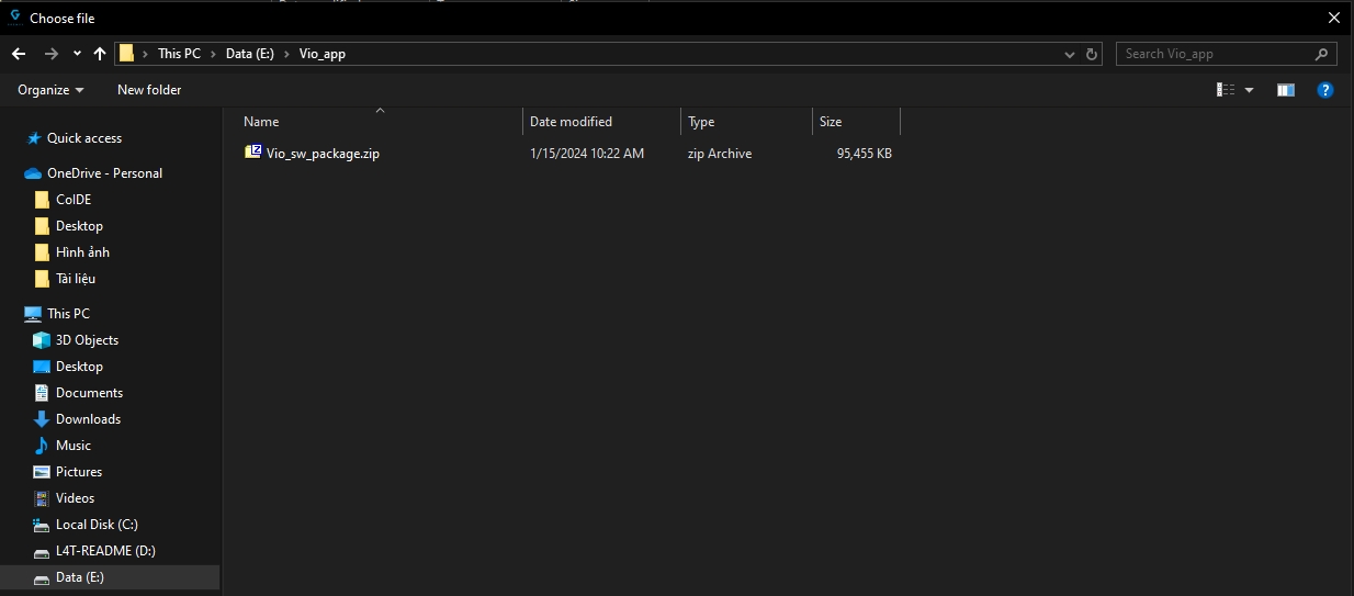
Configure the ZIO IP to stream and control over Ethernet
1. Overview
To stream video over Ethernet, the Zio payload needs to be set up in the same network layer (IP) as the remote-running QGC.
The default Zio payload is set to static IP address 192.168.12.240.
There are 2 ways for Remote to receive video from Zio:
Keep Zio's default setup (ip 192.168.12.240) andremote- Remote's IP setting at 192.168.12.200
2. Zio Ethernet Video Stream Protocol
On firmware v2.0.0 or higher, Zio streams video via RTP protocol and h264 encoder.
3. Set IP address of Zio and IP adress of UDP stream receiver
Take out the micro SD card from Zio
Connect and open the SD folder
Create file payload_setup.txt in the micro SD card folder
File name: payload_setup.txt File Content:
123456/*PAYLOAD CONFIGURATION*/ # IP address of PayloadZIO_ADDR = 192.168.12.200NETMASK = 255.255.255.0GATEWAY = 192.168.12.1
On the above example
Zio IP: 192.168.12.200
Insert the SD card containing the file payload_setup.txt into Zio and reboot.
Zio will set up according to the information in the file automatically.
NOTE: when Zio starts up without detecting the file payload_setup.txt in the memory card, Zio will automatically reset to the default IP (192.168.12.240)
Got video stream with QGroundControl app
General/Video setup as following
Got video stream with Gstreamer
In the case of using an embedded computer with the Gstreamer library, the video can be received via the command:
Change Zio's IP according to the network configuration of the running Remote system.
gst-launch-1.0 rtspsrc latency=0 location=rtsp://192.168.12.240:8554/zio ! rtph264depay ! decodebin ! videoconvert ! autovideosink sync=false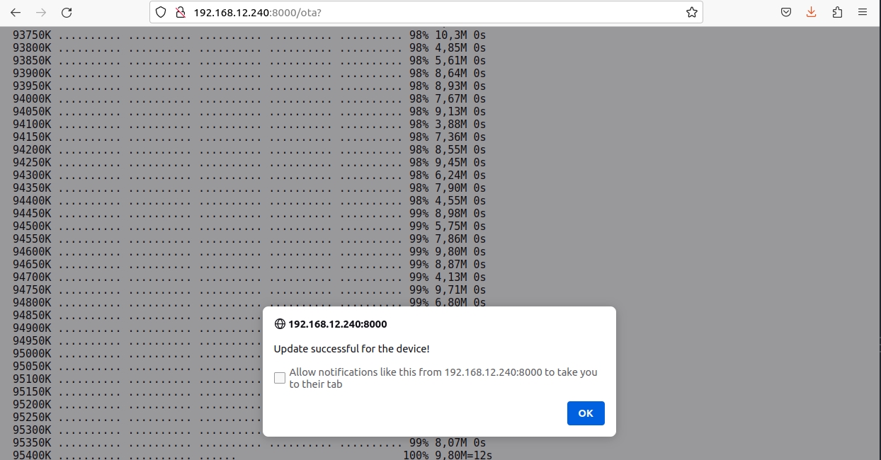
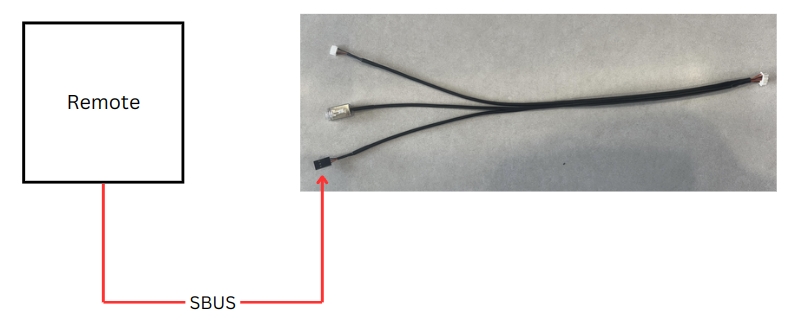

Table of contents
Version history
MAVLINK Messages
Set Camera Commands
Set Gimbal Commands
Get Payload Information
Message: COMMAND_LONG (76)
Message: PARAM_EXT_SET (323)
Message: PARAM_EXT_SET (323)
Message: PARAM_EXT_SET (323)
Message: PARAM_EXT_SET (323)
Message: PARAM_EXT_SET (323)
Message: COMMAND_LONG (76)
Message: COMMAND_LONG (76)
Message: PARAM_EXT_SET (323)
Message: COMMAND_LONG (76)
Message: COMMAND_LONG (76)
Message: COMMAND_LONG (76)
Message: COMMAND_LONG (76)
Message: PARAM_EXT_SET (323)
Message: PARAM_EXT_SET (323)
Message: PARAM_EXT_SET (323)
Message: PARAM_EXT_SET (323)
Message: PARAM_EXT_SET (323)
Message: PARAM_EXT_SET (323)
Message: PARAM_EXT_SET (323)
Message: PARAM_EXT_SET (323)
Message: PARAM_EXT_SET (323)
Message: PARAM_EXT_SET (323)
Message: GIMBAL_DEVICE_SET_ATTITUDE (284)
Message: GIMBAL_DEVICE_SET_ATTITUDE (284)
Message: COMMAND_LONG (76)
Message: COMMAND_LONG (76)
Message: COMMAND_LONG (76)
Message: COMMAND_LONG (76)
Message: COMMAND_LONG (76)
confirmation
uint8_t
1
param2
float
0 1
Photo mode Video mode
param_value
char[128]
"0" "1" "2" "5"
Record both Record EO Record IR Record OSD
param_type
uint8_t
UINT32
MAV_PARAM_EXT_TYPE
param_value
char[128]
"0" "1" "2" "3" "4"
EO/IR Only EO Only IR IR/EO Sync
param_type
uint8_t
UINT32
MAV_PARAM_EXT_TYPE
param_value
char[128]
"0" "2"
Combine Super Resolution
param_type
uint8_t
UINT32
MAV_PARAM_EXT_TYPE
param_value
char[128]
"0" "1" "2" "3" "4" "5" "6" "7" "8" "9" "10" "11" "12" "13" "14" "15"
1X 2X 4X 6X 8X 10X 12X 14X 16X 18X 20X 22X 24X 26X 28X 30X
param_type
uint8_t
UINT32
MAV_PARAM_EXT_TYPE
param_value
char[128]
"0" "1" "2" "3" "4" "5" "6"
1X 10X 20X 40X 80X 120X 240X
param_type
uint8_t
UINT32
MAV_PARAM_EXT_TYPE
confirmation
uint8_t
1
param1
float
0 1 2
ZOOM_TYPE_STEP ZOOM_TYPE_CONTINUOUS ZOOM_TYPE_RANGE
param2
float
-1 for wide, 1 for tele -1 for wide, 1 for tele, 0 to stop zooming A percentage value between 0.0 and 100.0
Zoom one step increment Continuous zoom up/down until stopped Zoom value as proportion of full camera range
confirmation
uint8_t
1
param1
float
1 4
FOCUS_TYPE_CONTINUOUS FOCUS_TYPE_AUTO
param2
float
-1: focusing in, 1: focusing out, 0: stop
Continuous focus up/down until stopped
param_value
char[128]
"0" "1" "2" "3" "4" "5" "6" "7" "8" "9"
F1: WhiteHot ; G1: WhiteHot F1: BlackHot ; G1: Fulgurite F1: Rainbow ; G1: IronRed F1: RainbowHC ; G1: HotIron F1: Ironbow ; G1: Medical F1: Lava ; G1: Arctic F1: Arctic ; G1: Rainbow1 F1: Globow ; G1: Rainbow2 F1: Gradedfire ; G1: Tint F1: Hottest ; G1: BlackHot
param_type
uint8_t
UINT32
MAV_PARAM_EXT_TYPE
confirmation
uint8_t
1
param2
int
Default, min: 0
Desired elapsed time between two consecutive pictures (in seconds)
confirmation
uint8_t
1
confirmation
uint8_t
1
confirmation
uint8_t
1
param_value
char[128]
"2" "3"
On Off
param_type
uint8_t
UINT32
MAV_PARAM_EXT_TYPE
param_value
char[128]
"0" "1"
Off On
param_type
uint8_t
UINT32
MAV_PARAM_EXT_TYPE
param_value
char[128]
"0" "1" "2" "3"
Lowest Low Mid High
param_type
uint8_t
UINT32
MAV_PARAM_EXT_TYPE
param_value
char[128]
"0" "3" "10" "11" "13"
Auto Manual Shutter Iris Bright
param_type
uint8_t
UINT32
MAV_PARAM_EXT_TYPE
param_value
char[128]
"13" "14" "17" "20" "21" "25" "26" "27" "28" "30"
1/10 1/20 1/50 1/100 1/125 1/500 1/725 1/1000 1/1500 1/2000
param_type
uint8_t
UINT32
MAV_PARAM_EXT_TYPE
param_value
char[128]
0
Aperture value can be set from 0 to 25, step 1
param_type
uint8_t
UINT32
MAV_PARAM_EXT_TYPE
param_value
char[128]
0
Bright value can be set from 0 to 41, step 1
param_type
uint8_t
UINT32
MAV_PARAM_EXT_TYPE
param_value
char[128]
"0" "1" "2" "3" "4" "5"
Auto Indoor Outdoor One push ATW Manual
param_type
uint8_t
UINT32
MAV_PARAM_EXT_TYPE
param_value
char[128]
"0" "1" "2" "3" "4"
OFF LOCK FOLLOW MAPPING RESET
param_type
uint8_t
UINT32
MAV_PARAM_EXT_TYPE
param_value
char[128]
"0" "1"
Gremsy Standard
param_type
uint8_t
UINT32
MAV_PARAM_EXT_TYPE
float[4]
rad/s
mavlink_euler_to_quaternion(roll, pitch, yaw, q)
Quaternion components, w, x, y, z
angular_velocity_x
float
rad/s
NaN
X component of angular velocity (Roll)
angular_velocity_y
float
rad/s
NaN
Y component of angular velocity (Pitch)
angular_velocity_z
float
rad/s
NaN
Z component of angular velocity (Yaw)
float[4]
rad/s
NaN
Quaternion components, w, x, y, z
angular_velocity_x
float
rad/s
Speed roll
X component of angular velocity (Roll)
angular_velocity_y
float
rad/s
Speed pitch
Y component of angular velocity (Pitch)
angular_velocity_z
float
rad/s
Speed yaw
Z component of angular velocity (Yaw)
confirmation
uint8_t
1
confirmation
uint8_t
1
confirmation
uint8_t
1
confirmation
uint8_t
1
confirmation
uint8_t
1
1.0.0
06 Jan 2023
Add example to do Connect payload Add example to do Load payload settings Add example to do Set payload settings Add example to do Image capture with the payload Add example to do Video record with the payload Add example to do Get video streaming from payload
1.0.1
25 May 2023
Included Gremsy gSDK to communicate and control gimbal Add examples to move gimbal in Angle mode and Angular rate mode using Mavlink Gimbal Protocol v2
v1.1.0
30 July 2024
Add some examples Get LRF status for VIO Payload define
v2.0.0
16 Aug 2024
target_system
1
target_component
191
MAV_COMP_ID_ONBOARD_COMPUTER
chan
0
MAVLink channel
target_system
uint8_t
1
System ID
target_component
uint8_t
101 (MAV_COMP_ID_CAMERA2)
MAVLINK Camera Component ID on Web setting
command
uint16_t
MAV_CMD_SET_CAMERA_MODE (530)
target_system
uint8_t
1
System ID
target_component
uint8_t
101 (MAV_COMP_ID_CAMERA2)
MAVLINK Camera Component ID on Web setting
param_id
char[16]
"C_V_REC"
target_system
uint8_t
1
System ID
target_component
uint8_t
101 (MAV_COMP_ID_CAMERA2)
MAVLINK Camera Component ID on Web setting
param_id
char[16]
"C_SOURCE"
target_system
uint8_t
1
System ID
target_component
uint8_t
101 (MAV_COMP_ID_CAMERA2)
MAVLINK Camera Component ID on Web setting
param_id
char[16]
"C_V_ZM_MODE"
target_system
uint8_t
1
System ID
target_component
uint8_t
101 (MAV_COMP_ID_CAMERA2)
MAVLINK Camera Component ID on Web setting
param_id
char[16]
"C_V_ZM_SR_LV"
target_system
uint8_t
1
System ID
target_component
uint8_t
101 (MAV_COMP_ID_CAMERA2)
MAVLINK Camera Component ID on Web setting
param_id
char[16]
target_system
uint8_t
1
System ID
target_component
uint8_t
101 (MAV_COMP_ID_CAMERA2)
MAVLINK Camera Component ID on Web setting
command
uint16_t
MAV_CMD_SET_CAMERA_ZOOM (531)
target_system
uint8_t
1
System ID
target_component
uint8_t
101 (MAV_COMP_ID_CAMERA2)
MAVLINK Camera Component ID on Web setting
command
uint16_t
MAV_CMD_SET_CAMERA_FOCUS (532)
target_system
uint8_t
1
System ID
target_component
uint8_t
101 (MAV_COMP_ID_CAMERA2)
MAVLINK Camera Component ID on Web setting
param_id
char[16]
"C_T_PALETTE"
target_system
uint8_t
1
System ID
target_component
uint8_t
101 (MAV_COMP_ID_CAMERA2)
MAVLINK Camera Component ID on Web setting
command
uint16_t
MAV_CMD_IMAGE_START_CAPTURE (2000)
target_system
uint8_t
1
System ID
target_component
uint8_t
101 (MAV_COMP_ID_CAMERA2)
MAVLINK Camera Component ID on Web setting
command
uint16_t
MAV_CMD_IMAGE_STOP_CAPTURE (2001)
target_system
uint8_t
1
System ID
target_component
uint8_t
101 (MAV_COMP_ID_CAMERA2)
MAVLINK Camera Component ID on Web setting
command
uint16_t
MAV_CMD_VIDEO_START_CAPTURE (2500)
target_system
uint8_t
1
System ID
target_component
uint8_t
101 (MAV_COMP_ID_CAMERA2)
MAVLINK Camera Component ID on Web setting
command
uint16_t
MAV_CMD
target_system
uint8_t
1
System ID
target_component
uint8_t
101 (MAV_COMP_ID_CAMERA2)
MAVLINK Camera Component ID on Web setting
param_id
char[16]
"C_V_FLIP"
target_system
uint8_t
1
System ID
target_component
uint8_t
101 (MAV_COMP_ID_CAMERA2)
MAVLINK Camera Component ID on Web setting
param_id
char[16]
"C_V_DEFOG"
target_system
uint8_t
1
System ID
target_component
uint8_t
101 (MAV_COMP_ID_CAMERA2)
MAVLINK Camera Component ID on Web setting
param_id
char[16]
"C_V_DEFOG_LV"
target_system
uint8_t
1
System ID
target_component
uint8_t
101 (MAV_COMP_ID_CAMERA2)
MAVLINK Camera Component ID on Web setting
param_id
char[16]
"C_V_AE"
target_system
uint8_t
1
System ID
target_component
uint8_t
101 (MAV_COMP_ID_CAMERA2)
MAVLINK Camera Component ID on Web setting
param_id
char[16]
"C_V_SP"
target_system
uint8_t
1
System ID
target_component
uint8_t
101 (MAV_COMP_ID_CAMERA2)
MAVLINK Camera Component ID on Web setting
param_id
char[16]
"C_V_IrP"
target_system
uint8_t
1
System ID
target_component
uint8_t
101 (MAV_COMP_ID_CAMERA2)
MAVLINK Camera Component ID on Web setting
param_id
char[16]
"C_V_BrP"
target_system
uint8_t
1
System ID
target_component
uint8_t
101 (MAV_COMP_ID_CAMERA2)
MAVLINK Camera Component ID on Web setting
param_id
char[16]
"C_V_WB"
target_system
uint8_t
1
System ID
target_component
uint8_t
101 (MAV_COMP_ID_CAMERA2)
MAVLINK Camera Component ID on Web setting
param_id
char[16]
"GB_MODE"
target_system
uint8_t
1
System ID
target_component
uint8_t
101 (MAV_COMP_ID_CAMERA2)
MAVLINK Camera Component ID on Web setting
param_id
char[16]
"RC_MODE"
target_system
uint8_t
1
System ID
target_component
uint8_t
101 (MAV_COMP_ID_CAMERA2)
MAVLINK Camera Component ID on Web setting
target_system
uint8_t
1
System ID
target_component
uint8_t
101 (MAV_COMP_ID_CAMERA2)
MAVLINK Camera Component ID on Web setting
target_system
uint8_t
1
System ID
target_component
uint8_t
101 (MAV_COMP_ID_CAMERA2)
MAVLINK Camera Component ID on Web setting
command
uint16_t
MAV_CMD_REQUEST_CAMERA_INFORMATION (521)
target_system
uint8_t
1
System ID
target_component
uint8_t
101 (MAV_COMP_ID_CAMERA2)
MAVLINK Camera Component ID on Web setting
command
uint16_t
MAV_CMD_REQUEST_VIDEO_STREAM_INFORMATION (2504)
target_system
uint8_t
1
System ID
target_component
uint8_t
101 (MAV_COMP_ID_CAMERA2)
MAVLINK Camera Component ID on Web setting
command
uint16_t
MAV_CMD_REQUEST_STORAGE_INFORMATION (525)
target_system
uint8_t
1
System ID
target_component
uint8_t
101 (MAV_COMP_ID_CAMERA2)
MAVLINK Camera Component ID on Web setting
command
uint16_t
MAV_CMD_REQUEST_CAMERA_CAPTURE_STATUS (527)
target_system
uint8_t
1
System ID
target_component
uint8_t
101 (MAV_COMP_ID_CAMERA2)
MAVLINK Camera Component ID on Web setting
command
uint16_t
MAV_CMD_REQUEST_CAMERA_SETTINGS (522)
Replace gSDK by MAVLINK interface Provide MAVLINK command list Publish resource
MAV_CMD
"C_V_ZM_CB_LV"
MAV_CMD
MAV_CMD
MAV_CMD
MAV_CMD
MAV_CMD
MAV_CMD_VIDEO_STOP_CAPTURE (2501)
q
q
MAV_CMD
MAV_CMD
MAV_CMD
MAV_CMD
MAV_CMD