> For the complete documentation index, see [llms.txt](https://docs.gremsy.com/llms.txt). Markdown versions of documentation pages are available by appending `.md` to page URLs; this page is available as [Markdown](https://docs.gremsy.com/gimbals/pixy-lr/airpixel-entire-set-installation-for-cube-pilot-pixhawk.md).
# AIRPIXEL ENTIRE SET INSTALLATION FOR CUBE PILOT/PIXHAWK
Table of Contents
* Installation basics
* Mount Sony ILX-LR1 to Pixy-LR gimbal
* Installation of the ENTIRE with Pixy-LR wiring set
* USB configuration for EXIF geotagging
* WiFi configuration for control
## **Installation basics**
Here is a list of cables you will need for connection of Sony ILX-LR1 mounted on Pixy-LR gimbal together with the Pixhawk / Ardupilot / Cube flight controller for geotagging and control of the camera.
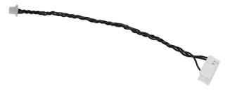
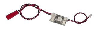
COM4-MavLink cable
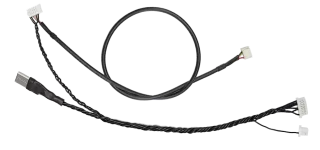
Pixy-LR connection harness:
uBEC with power cables:
## **Mount Sony ILX-LR1 to Pixy-LR gimbal**
**STEP 1**\
Mount the camera per Gremsy manual.
Process is very easy:
* Use included screws to mount the camera body
* Attach box with USB & HDMI connector and mount by srew
* Aach cable to Molex 6 pin connector
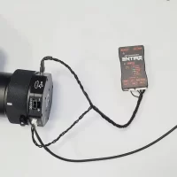
## **Installation of the ENTIRE with Pixy-LR wiring set**
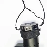
**STEP 1**\
Use Pixy-LR connection harness cable and connect 7pin connector to CTRL port on gimbal quickrelease.
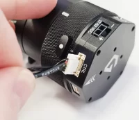
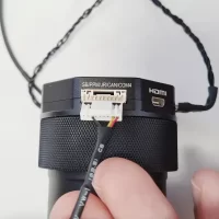
**STEP 2**\
Connect the USB-C end of the harness to USB-C port of the gimbal.
Connector is bent in 90 deg and should be oriented to the top.
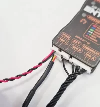
**STEP 3**\
Connect other end of the harness to the ENTIRE
* 9 pin connector to the ENTIRE USBMULTI connector
* 3 pin connector to the ENTIRE EXT port
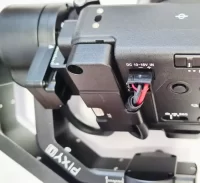
**STEP 4**\
Use COM4-MavLink cable (photo on the top) and connect to the gimbal Quick Release
**STEP 5**\
Other end of COM4-MavLink cable connect to the ENITRE UNI-C port
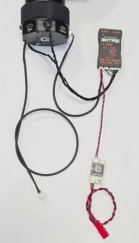
**STEP 6**\
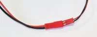
Use pre-connected uBEC set and connect JST SH 2pin end of the set and connect to the ENTIRE PWR port
**STEP 7**\
At this point we have almost all important connections between the Pixy-LR and the ENTIRE ready
**STEP 8**\
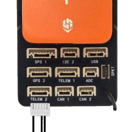
Connect MavLink end of Pixy-LR connection harness to PixHawk flight controller.
**STEP 9**\
Connect power to the ENTIRE and Pixy-LR gimbal.\
**Check polarity!**
ENTIRE and the gimbal needs separate power connections. ENTIRE’s uBEC accepts 7 – 23V and needs at least 1 Amp of current available. [More information here](https://airpixel.cz/docs/power-adaptor-ubec/).
For Pixy-LR power requirements please follow gimbal manual.
**STEP 10**
You have two options how to use our system in cooperation with Gremsy:
1. You will use ENTIRE & MavCam only control tilt / yaw of the gimbal via HereLink hw wheel / on-screen joystick.
* In this case is setting simple:
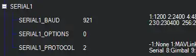
* SERIAL1\_PROTOCOL: “Mavlink2”
* SERIAL1\_BAUD: “921600“
* MNT1\_TYPE: “0”
* MNT2\_TYPE: “0
2. Use new Ardupilot gimbal control fatures (like point gimbal automatically)
* In this case, gimbal will be controlled by the Cube and ENTIRE & MavCam will command Cube directly to control attitude of the gimbal. For this case you have to set:
* SERIAL1\_PROTOCOL: “Mavlink2”
* SERIAL1\_BAUD: “921600“
* MNT1\_DEFLT\_MODE: “3”
* MNT1\_TYPE: “6”
* RC6\_OPTION: “214”
* RC7\_OPTION: “212”
* RC8\_OPTION: “213”
* MNT1\_RC\_RATE: “90”
3. For newest Ardupilot firmwares you need to set:
* **CAM1\_TYPE: “5”**
* If you do not have this option in your Ardupilot firmware parameters, ENTIRE will work by default.
**(IF YOU USED TELEM2, USE SERIAL2 | MNT2)**
Baudrate!Use SERIALx\_BAUD 921600 in all cases, even if Gremsy manual suggest lower value, use 921600bps. It is because ENTIRE transfers lots of additional information via communication line so bandwidth is important.Other configuration!Configuration may change over time, please check Gremsy manuals for more information.
**STEP 11**
* Connect your gimbal to gTune app in your phone or PC
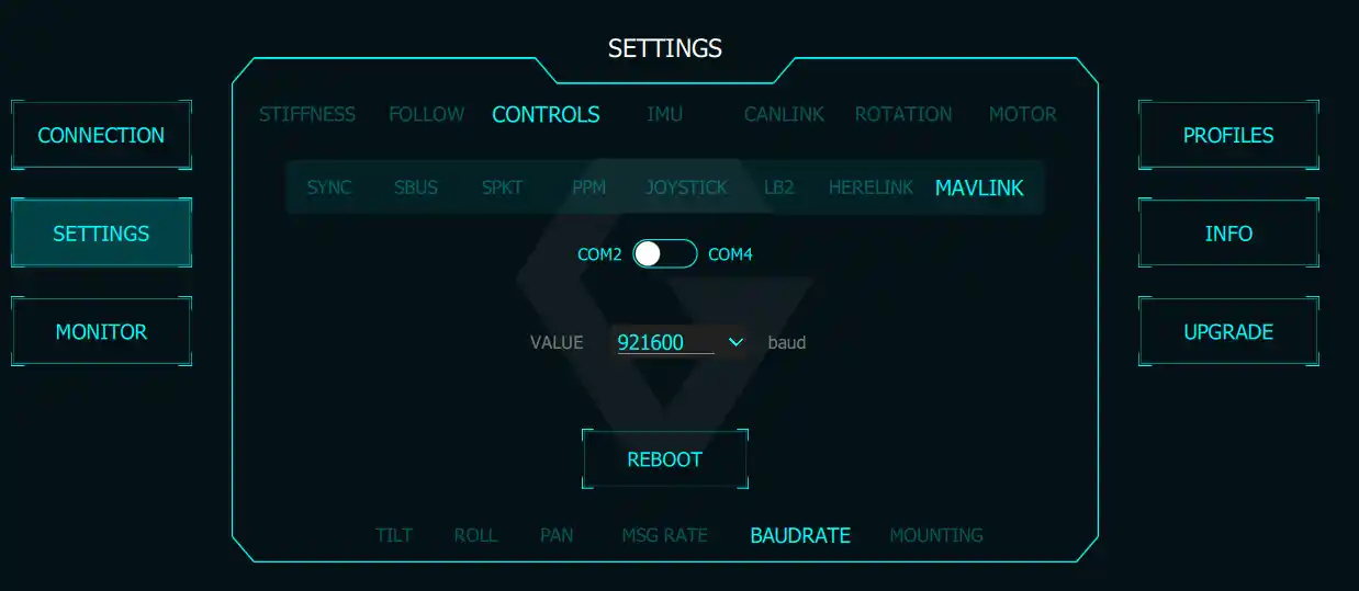
* Navigate to SETTINGS->CONTROLS->MAVLINK
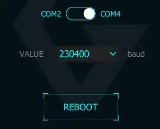
* Configure COM2 baudrate to 921600bps (used for connection to Cube)
* Configure COM4 baudrate to 230400bps (used for ENTIRE connection)
**STEP 12**
* Navigate to SETTINGS->CONTROLS->MAVLINK
* Configure COM4 baudrate to 230400bps (used for ENTIRE connection)
* Make sure you clicked **REBOOT** after each change
**STEP 13**
* Open Entire’s configuration page ([how to](https://airpixel.cz/docs/entire-first-steps/#1-toc-title))
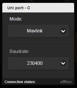
* Open ENTIRE’s MENU web page and set UNI-C port to
* MavLink mode
* 230400 bps
**STEP 14**
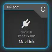
* If all configuration was done properly, you will get UNI-C “online” and see
* GPS information update speed
* ATTI information update speed
* Gimbal angle readings (P-pitch / Y-yaw)
* (YAW information is absolute heading)
* If port C is not “online”, do not use other baudrates or other port modes. Re-check baudrate settings in the gimbal and the ENTIRE, reboot all systems.
**STEP 15**
* Open MENU -> (geotagging) Settings
* From the list select “GPS data preview”
* In the popup you should get similar data if the GPS / RTK has enough signal.
* Data preview popup is real-time and should change as drone / gimbal moves.
## **USB configuration for EXIF geotagging**
**STEP 1**
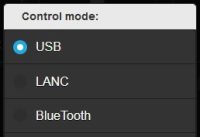
* ENTIRE needs to be set to “**USB Control**” mode and updated to the latest firmware to have this procedure working.
* Navigate to **MENU->Capture detection** and set to “**Hotshoe sync**” – important for high acurracy and reliability!
[](https://airpixel.cz/wp-content/uploads/2023/11/usb-control-mode.jpg)[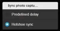](https://airpixel.cz/wp-content/uploads/2024/01/hotshoesync.webp)
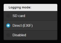
**STEP 2**\
Enable GeoTagging via ENTIRE **MENU->Logging mode-> Direct EXIF**
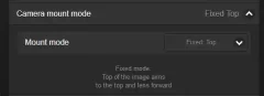
**STEP 3**\
Select camera mount mode to fixed mount depending on your mount of the camer in the drone
* FIXED TOP
Camera top is aiming top and lens is looking in direction of the flight
* FIXED FORWARD
Camera top is aiming in direction of the flight and lens is looking straight down
* FIXED LEFT/RIGHT
Camera top is aiming left or right and the lens is looking straight down
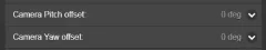
**STEP 4**\
Select camera Pitch / Yaw offset if camera is not fixed in 90degree offset steps
* This step is optional and usually can be skipped
**STEP 5**pen the MENU -> (Geotagging) Settings
* Scroll down to Other features
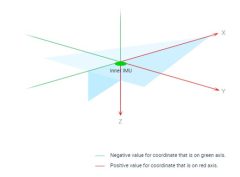
* And insert X, Y, Z offsets.
* When **GPS** is used, offset is counted from body center (if correct offset is configured in the FC). If your flight controller does not have configured antennas offsets, configure offset from the camera to the antenna.
* When **RTK** is used, offset is counted from body center (if correct offset is configured in the FC). If your flight controller does not have configured antennas offsets, configure offset from the camera to the **antenna A**.
Offsets are in millimeters!
[](https://airpixel.cz/wp-content/uploads/2021/12/offset_polarity.jpg)[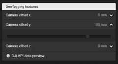](https://airpixel.cz/wp-content/uploads/2021/12/offsets.jpg)
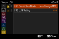
**STEP 6** Open camera MENU and navigate to:\
**SETUP->USB->USB Connection Mode->MassStorage**\
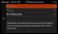
**STEP 7**
Open camera MENU and navigate to:\
**NETWORK->Cnct./PC Remote->PC Remote Function->OFF**
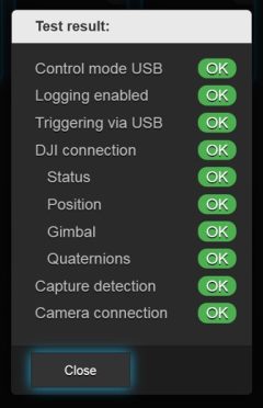
**STEP 8 – GEOTAGGING TEST**
* Your setup is ready to be used for geotsagging at this point
* ENTIRE has Self-Test routines for GeoTagging to easily check if all wiring is working well
* Make sure that all equipment is turned ON and camera is set to MASS STORAGE MODE
* Click to MENU->Configuration test and let the Entire to do a self-test
* At the beginning of the test, one photo will be triggered
* Entire will check if HotShoe sensor has properly recognized trigger
* Entire will check all necessary input data connections
* In case of any problems, result will provide hints to solve the issue
* Test photo will not be geotagged in the test method!
## **WiFi configuration for control**
**STEP 1**
Open camera MENU and navigate to\
**NETWORK->Network Option->Access Authen. Settings**\
Open this item and in submenu DISABLE authentication\
Confirm all warnings OK\
Access Authen. Settings should be **OFF**
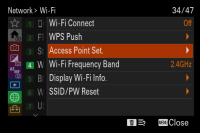
**STEP 2**
Navigate to:\
**NETWORK->Wi-Fi->Access Point Set**\
And enter item\
Wait for scan of available accesspoints
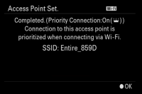
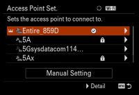
**STEP 3**
From the list of networks, select Accesspoint of the ENTIRE\
**Entire\_xxxx**\
**Confirm OK**
**STEP 4**
Camera will connect the ENTIRE via WiFi now\
Once done, **confirm OK for return to the list**
**STEP 5**
Click right (MANUAL SETTINGS) on the ENTIRE’s WiFi item to enter manual IP settings\
**Scroll to IP Address settings “Auto” and change to “Manual”**
[](https://airpixel.cz/wp-content/uploads/2023/11/WiFi-select-1.png)[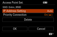](https://airpixel.cz/wp-content/uploads/2023/11/WiFi-manual.png)
**STEP 6**
Fill IP addresses and masks:
**192.168.122.1**\
**255.255.0.0**\
**192.168.10.1**
Confirm OK
Camera will now re-connect the ENTIRE
[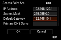](https://airpixel.cz/wp-content/uploads/2023/11/WiFi-IP.png)[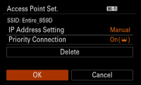](https://airpixel.cz/wp-content/uploads/2023/11/WiFi-confirmmanula.png)
**STEP 7**
Once connection is done, scroll up to **“Wi-Fi Connect” and turn it ON**
[](https://airpixel.cz/wp-content/uploads/2023/11/Wifi_ON.png)[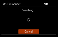](https://airpixel.cz/wp-content/uploads/2023/11/WiFi-searching.png)[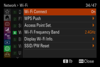](https://airpixel.cz/wp-content/uploads/2023/11/Wifi_ON-1.png)
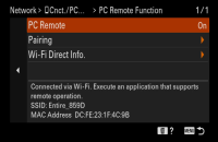
**STEP 8**
Navigate to:\
**NETWORK->Cnct./PC Remote->PC Remote Function->ON**
[](https://airpixel.cz/wp-content/uploads/2023/11/PCremoteON.png)
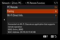
**STEP 9**
Now scroll to **PAIRING** and enter item
Wait for initialization
Once pairing confirmation for the ENTIRE shows, confirm OK
**\*\*\* YOU HAVE TO REPEAT THIS STEP AFTER EACH UPDATE OF THE ENTIRE FIRMWARE \*\*\***
[](https://airpixel.cz/wp-content/uploads/2023/11/WiFi-PCremoteON.png)[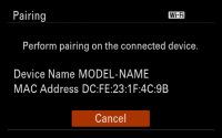](https://airpixel.cz/wp-content/uploads/2023/11/WiFi-pairing-1.png)[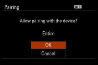](https://airpixel.cz/wp-content/uploads/2023/11/WiFi-pairing-2.png)[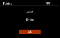](https://airpixel.cz/wp-content/uploads/2023/11/WiFi-pairing-OK.png)
**STEP 10 – EXPOSURE CONTROL TEST**
WiFi control should be now available together with the geotagging via USB. You can control exposure values via MavCam / ENTIRE’s web page, AIR Commander Link or MissionPlanner plugin.
{% hint style="info" %}
Remember to turn the camera OFF by power off switch! DO NOT DISCONNECT POWER otherwise all setings will be lost and you will have to start over!Firmware updatePairing needs to be done again after ENTIRE's firmware update!Info!WiFi connection is not initiated by the ENTIRE, camera is responsible for re-connection after reboot. ENTIRE is only "available" for camera connection. Thanks to this is connection stable and does not break ENTIRE's hotspot presence during setup.
{% endhint %}
---
# Agent Instructions
This documentation is published with GitBook. GitBook is the documentation platform designed so that both humans and AI agents can read, navigate, and reason over technical content effectively. Learn more at gitbook.com.
## Querying This Documentation
If you need additional information that is not directly available in this page, you can query the documentation dynamically by asking a question.
Perform an HTTP GET request on the current page URL with the `ask` query parameter, and the optional `goal` query parameter:
```
GET https://docs.gremsy.com/gimbals/pixy-lr/airpixel-entire-set-installation-for-cube-pilot-pixhawk.md?ask=&goal=
```
`ask` is the immediate question: it should be specific, self-contained, and written in natural language.
`goal` is optional and describes the broader end goal you are ultimately trying to accomplish on behalf of the user. GitBook uses it to tailor the answer towards what is most useful for that goal.
The response will contain a direct answer to the question and relevant excerpts and sources from the documentation.
Use this mechanism when the answer is not explicitly present in the current page, you need clarification or additional context, or you want to retrieve related documentation sections.


 ](https://airpixel.cz/wp-content/uploads/2023/11/usb-control-mode.jpg)[](https://airpixel.cz/wp-content/uploads/2024/01/hotshoesync.webp)
**STEP 2**\
Enable GeoTagging via ENTIRE **MENU->Logging mode-> Direct EXIF**
](https://airpixel.cz/wp-content/uploads/2023/11/usb-control-mode.jpg)[](https://airpixel.cz/wp-content/uploads/2024/01/hotshoesync.webp)
**STEP 2**\
Enable GeoTagging via ENTIRE **MENU->Logging mode-> Direct EXIF**